Zone 1 (Schmierstrang 1)
Zone 2 (Schmierstrang 2)
M
„p“ digital
„p“ digital
„p“ digital
„p“ digital
„p“
digital
KD
KD
Verteiler VSL2
Verteiler VSL2
FK-Pumpe
Zone
1
Zone
2
I 1
I 2
I 3
I 6
I 8
LL=I 7
Ø 1
Ø 2
Ø 3
Ø 4
Ø 8
300
bar
I 4
I 5
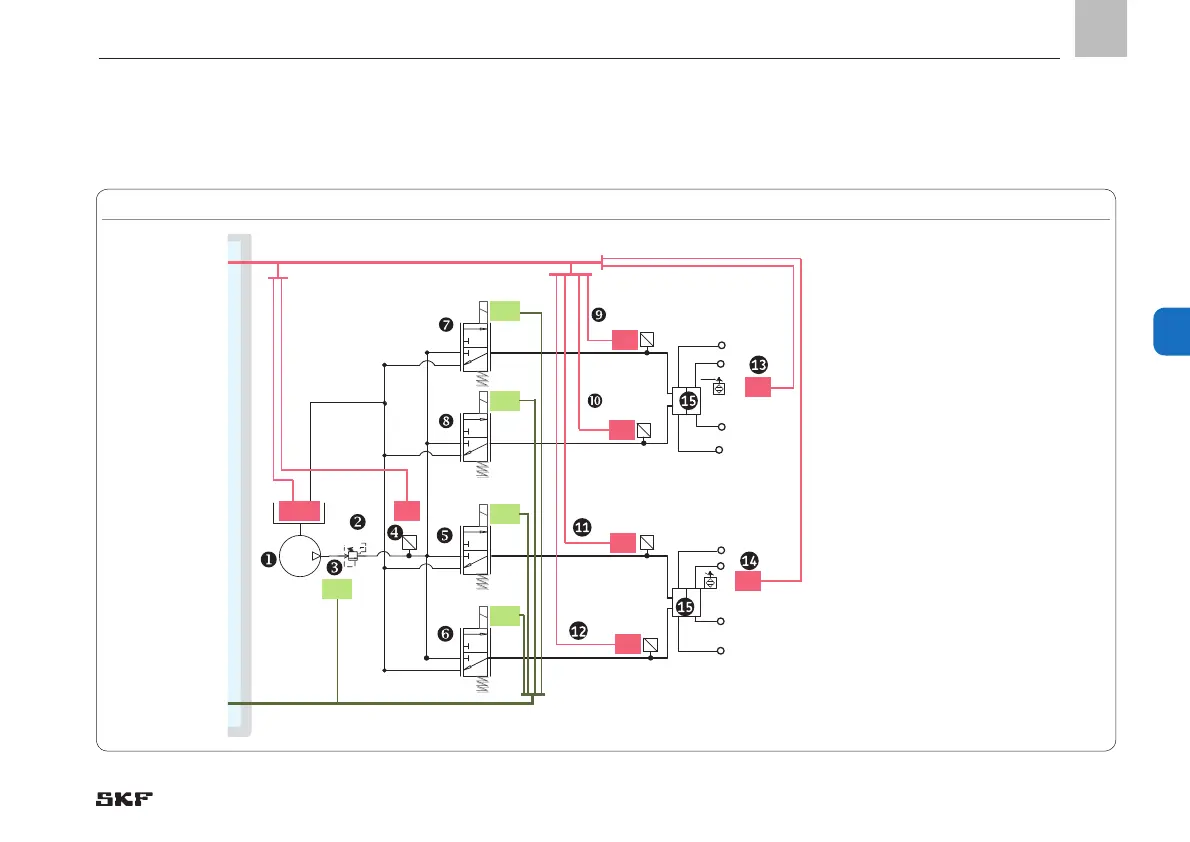
Control circuits
Power supply for
pump
to terminal strip X4
Supply circuit A8
Pump motor,
max. 8 amp.
Control circuits A1 and A2 = 3/2 reversing valves for zone 1 and model DDS50 digital differential pressure switch
Monitoring zone 1
I 1 and I 2 = DDS50 digital differential pressure
switch
Main line 1 and main line 2
I 3 = Feeder monitoring
(piston detector)
Monitoring zone 2
I 4 and I 5 = DDS50 digital differential pressure
switch
Main line 1 and main line 2
I 6 = Feeder monitoring
(piston detector)
Control circuits A3 and A4 = 3/2 reversing valves for zone 2
Control circuit A6
Relief valve
EN
65
6