-9-
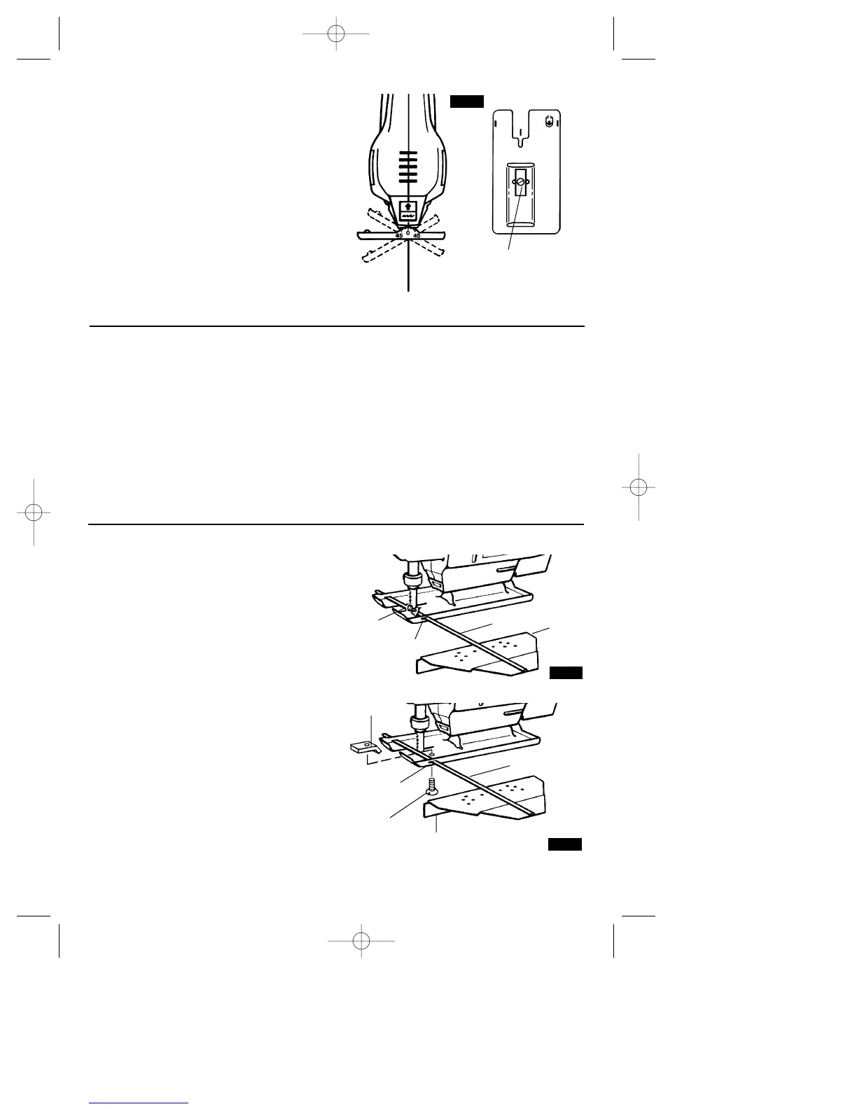
BEVEL OR ANGLE CUTTING
Disconnect the cord from the power source.
The foot can be adjusted to cut any angle
from 0˚ to 45˚. TO ADJUST: Loosen the foot
adjustment screw in the bottom of foot with a
flat-tip screwdriver. Position foot to desired
angle and securely tighten screw. After
adjusting foot, make a sample cut to check
the angle (Fig. 6).
FIG. 6
BACK VIEW
BOTTOM VIEW
FOOT
ADJUSTMENT
SCREW
METAL CUTTING
When cutting metal clamp material down. Be
extra certain that you move the saw along
slowly. Use lower speeds. Do not twist, bend,
or force the blade. If the saw jumps or
bounces, use a blade with finer teeth. If the
blade seems clogged when cutting soft
metal, use a blade with coarser teeth.
For easier cutting, lubricate the blade with a
stick of cutting wax, if available, or with
kerosene when cutting aluminum or cutting
oil when cutting steel. Thin metal should be
sandwiched between two pieces of wood or
tightly clamped on a single piece of wood
(wood on top of the metal). Draw the cut lines
or design on the top piece of wood.
When cutting aluminum extrusion or angle
iron, clamp the work in a bench vise and saw
close to the vise jaws.
When sawing tubing and the diameter is
larger than the blade is deep, cut through the
wall of the tubing and then insert the blade
into the cut rotating the tube as you saw.
RIP FENCE AND CIRCLE CUTTING GUIDE
This accessory is available at an extra cost. It
is used for fast and accurate straight and
circle cutting (Fig. 7a & 7b).
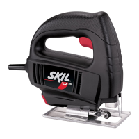
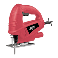
ATTACHING RIP FENCE
1. Insert bar of rip fence through the slots
provided in foot, from either side of foot with
the edge guide facing down (Fig. 7a & 7b).
OLD STYLE FOOT
2. Thread the clamp screw through threaded
hole in tab on left side of foot, and securely
tighten clamp screw with a screwdriver
against rip fence bar (Fig. 7a).
NEW STYLE FOOT
2. Thread the clamp screw from bottom side
of foot through the threaded hole and thread
into the clamp on left side of foot, and
securely tighten clamp screw with a
screwdriver, to clamp the rip fence bar in
place (Fig. 7b).
FIG. 7b
EDGE GUIDE
DOWN
BAR
CLAMP
SLOT
CLAMP
SCREW
FIG. 7a
EDGE
GUIDE
DOWN
BAR
CLAMP
SCREW
SLOT
SM 2610995772 8/00 9/14/00 8:53 AM Page 9