14
Router Table Setup
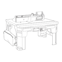
ALTERNATE METHOD 2
(Figs. 12 and 13)
1. Cut a board 18
1
⁄
4
" wide x 23" long from
a piece of 3/4" thick wood or plywood.
2. Center the router table (A) on the board and
mark the location of the four mounting holes
(two on each leg assembly [8 and 10]).
3. Remove the router table (A) from the
workbench and set it aside.
4. Drill suitable pilot holes (for wood screws)
or through-holes (for machine screws) at
the marked locations.
5. Place the router table (A) on the board and
align the mounting holes in the router table
legs (8 and 10) with the holes drilled in the
board.
6. Secure the router table (A) in place
using the wood screws and washers (not
provided). Applying a thin coat of soap to
the screw threads will make it easier to
thread the screws into the pilot holes.
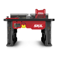
7. Secure the board to a workbench or other
sturdy surface with screws (Fig. 12) or
clamps (Fig. 13) during use.
IMPORTANT: Be sure the placement of
the clamps will not interfere with operation
of the router table.
10
8
A
FIG. 12
FIG. 13
10
8
A
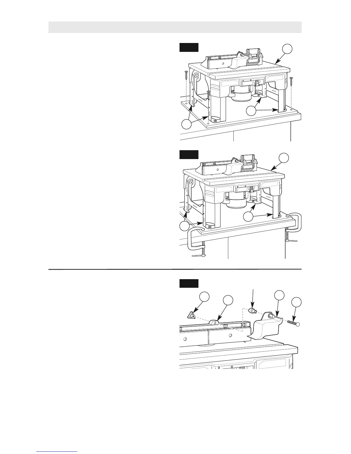
OVERHEAD GUARD ASSEMBLY
(Fig. 14)
The overhead guard assembly (15) comes
preinstalled on the fence assembly. Some
routing applications will require you to remove
this guard.
1. Loosen and remove clamping knob (18) on
the top back of the fence assembly (C).
2. Slide the 1/4-20 x 2½" carriage bolt (33),
overhead guard (15), and spacer from
the fence assembly (C).
3. Reinstall the overhead guard assembly (15)
by following these steps in reverse.
FIG. 14
18
C
15
33
Spacer
 Loading...