16
5. Set the motor housing upside down on the motor-housing top cap with the collet pointing up
and remove the bit.
WARNING
Always remove the cutter bit from collet/nut when the router is not being
used. Leaving bits installed could result in accidents causing serious
personal injury.
Adjusting the Depth of Cut
WARNING
Your router should never be turned on or be connected to the power
source when you are assembling parts, making adjustments, installing or
removing collets/nuts, cutter bits, cleaning the product, or when it is not in use. Disconnecting
the router will prevent accidental starting, which could cause serious personal injury.
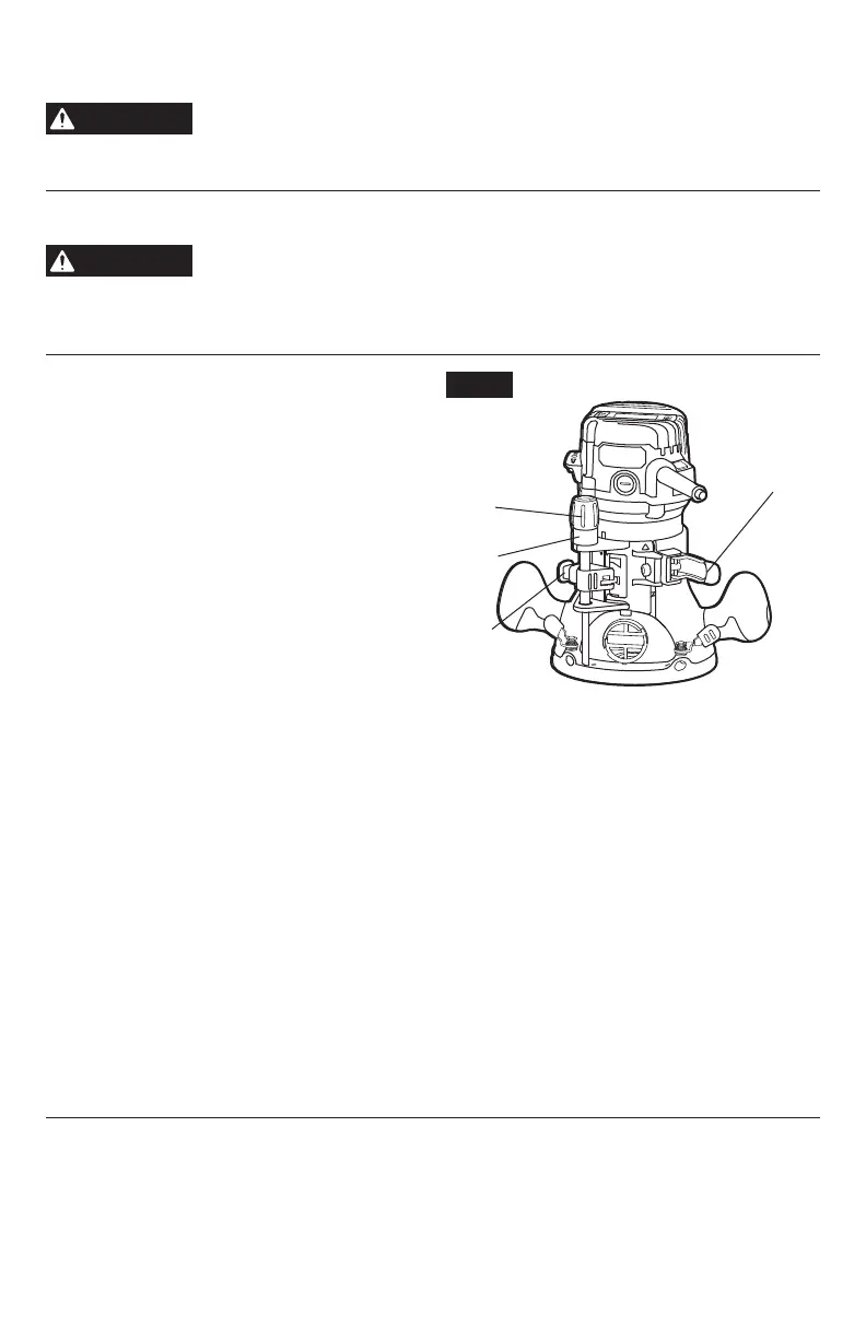
Depth Adjustment With Fixed
Base (FIG. 6)
Notice:
All depth adjustments on the xed
base must be made with the motor clamp
open.
Notice:
For all xed base routers, the cutter bit
depth equals the amount of the cutter that is
exposed below the surface of the sub-base.
The xed base is designed with a micrometer-
ne adjustment system. When the bit is
lowered to the approximate position desired
(coarse setting), the system then can be micro-
adjusted to the precise depth required.
Coarse Adjustment
Depressing the coarse-adjustment knob (B) allows you to quickly lower or raise the cutter bit
to an approximate depth setting.
Fine Adjustments
NOTICE:
Be sure that the micrometer-ne adjustment system is engaged before making ne
adjustments. Test it by turning the ne-adjustment dial (C) clockwise and counter-clockwise to
see if the bit lowers and raises.
The depth-indicator ring (D) located on the ne-adjustment dial is marked in 1/256- inch
increments. Turning the ne-adjustment dial counterclockwise 180° (1/2 turn), lowers the
cutter bit 1/32 inch. One full turn counterclockwise 360° (zero “0” to zero “0”) lowers the bit
1/16 inch.
NOTICE:
The depth-indictor ring (D) may be reset to zero “0” without moving the ne-
adjustment dial. This allows the user to begin adjustments from any reference point desired.
NOTICE:
Making a single, deep cut is never advisable. Smaller diameter cutter bits are easily
broken by too much side thrust and torque. Larger cutter bits will cause a rough cut and be
difcult to guide and control. For these reasons, do not exceed 1/8-in. depth of cut in a single
pass.
Fig. 6
D
B
A
C
 Loading...