Check that the transducer sensor housing, when fully inserted, is ush with the lower surface of the bottom
ange.
If the above point are not met exactly, it is possible to adjust the height of the gate valve by inserting
thicker or more than one “Klingersil” gaskets, alternatively changing the 1.5 mm gasket to a 0.5 mm gasket.
After the gate valve has been adjusted correctly, remove the sensor housing element.
Place the O-ring, item # 13, in the groove on top of the intermediate element. Apply grease to the O-ring.
Assemble sensor housing. Secure with 6 each washers / nuts.
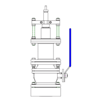
Insert the 2 safety bolts item # 16 through the ange and secure with Nuts ( M16 counternuts )
NOTE !
The 2 safety bolts MUST be used during removal and installation of sensor elements when the ship is
aoat.
ASSEMBLY OF SENSOR HOUSING.
Place transducer element in the bottom of the sensor housing, item # 4.
Slide the pressure tube, item # 5, over the cable and place it on top of the transducer element.
Place the Nitril 3 mm gasket, item # 15, on top of the sensor housing.
Check that the top edge of the pressure tube is level with the top surface of the Nitril gasket.
If not, adjust with 1 mm shims plates between pressure tube and transducer element.
Place the top ange, item # 6, on top of the Nitril gasket and secure with 4 each 10 mm bolts and washers.
Install the washers, rubber gasket and bronze nut, items # 19, 20 and 21,
in the cable gland and tighten until the cable can not be moved in the cable gland.
Add washers if necessary.
The transducer housing is now ready to be installed in the gate valve.
To remove the transducer element, reverse the procedure.
 Loading...