Dokument Art.Nr. 97000101 ~ 12 ~
Installation instructions BS2012 (continued)
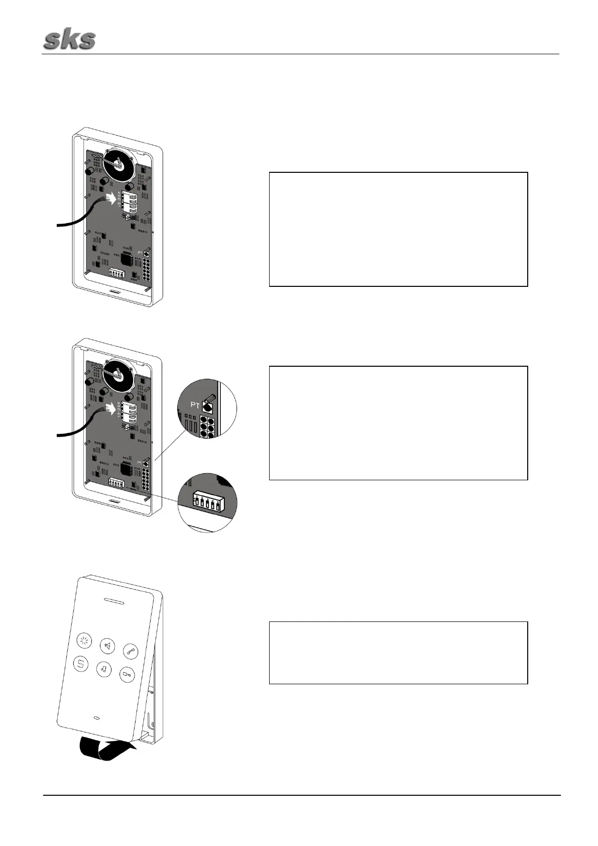
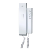
Insert the wire to the terminal as drawn in the wiring
plan. After supplying the supply voltage the 6 keys of
the intercom unit are calibrated. This process is
indicated by alternating flashing of the middling and
right LED on the front. Meanwhile please don't touch
one of the buttons.
Set the SKS-BUS call address at the intercom unit.
Each address is assigned to a bell push button on the
door unit. The addresses are listed in the annex. In
general, the SKS-BUS call address "A1" is the one to
start with.
When replacing intercom units, set the DIP-switch to
match the previously mounted intercom unit.
The front panel needs to be pushed against the rear
panel until the clips snap into place. Make sure that no
bare wires can touch the circuit board from behind.