14 15
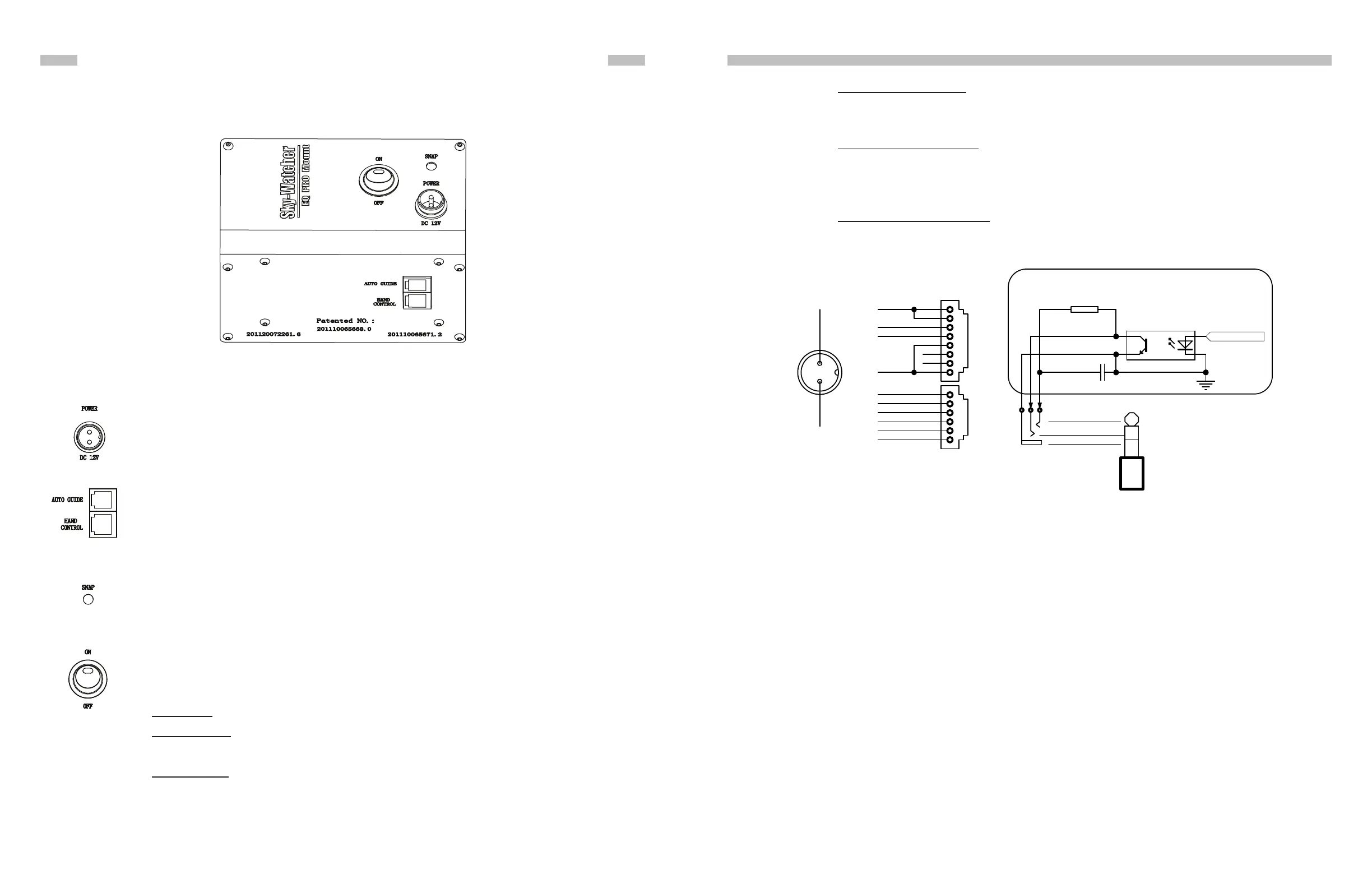
3.1 Control Panel
The control panel of the EQ8 Mount is shown below:
Fig. 3.1
3.2 Panel Interface Components:
PART III : ELECTRONIC CONTROL INTERFACE
POWER: This is an outlet from which the mount and the hand control get power
supply. To connect to a power supply, align the index on both the plug of the cord
and the outlet on the panel, and then insert the plug to the outlet. Tighten the
knurled cap on the plug to secure the plug on the panel.
AUTO GUIDE: This RJ-12 6-pins outlet is for connecting an autoguider. It is com-
patible with any autoguider with a ST-4 type interface.
HAND CONTROL: This RJ-45 8-pins outlet is for connecting the SynScan hand
controller.
SNAP:This is a stereo outlet for connecting to a camera’s shutter control port. The
SynScan hand control can control a camera to take pictures automatically via this
interface.
POWER Switch: Turns on and off the power to the mount and hand controller.
The power LED on the power switch serves as a power-on indicator and provides
other statuses.
1. Steady on: Power voltage is normal.
2. Slow ashing: Power voltage is low; continuing to operate the mount may dam-
age the battery (if a 12V lead-acid battery is in use).
3. Fast ashing: Power voltage is extremely low; continuing to operate the mount
may damage the battery and the motor controller in the mount.
4. Intermittent one ash: The PPEC training routine has been triggered, but the
controller in the mount has not received the worm index signal and the correc-
tion-recoding has not started yet.
5. Intermittent two ashes: The PPEC training routine has been started and the
controller in the mount has received the worm index signal and started to record
the PE correction. When the intermittent two ashes stops, it means the PPEC
training has nished.
6. Intermittent, three ashes: Sidereal tracking with PEC is now enabled.
3.3 Pinout of the Interfaces:
Fig. 4.3
PART III: ELECTRONIC CONTROL INTERFACE
Note:
• The SNAP port provides two trigger signals to the stereo plug. The signal to the head of the
plug is issued slightly later than the signal to the ring of the plug.
• For a camera which only needs a shutter-release signal, either trigger signals will work. For
a camera which requires a “Focus” signal ahead of the shutter-release signal, both signals
should be connected properly.
• The camera control cable shipped with the AZ-EQ6 GT mount is for a Canon EOS series
DSLR camera. Cable for other cameras is optional and can be ordered separately.
• Output Voltage: DC 11V (minimum) to DC 16V (maximum). Voltage not in this range might
cause permanent damage to the motor controller or the hand controller.
• Output Current: 4A for power supply with 11V output voltage, 2.5A for power supply with
16V output voltage.
• Do not use an un-regulated AC-to-DC adapter. When choosing an AC adapter, it is recom-
mended to use a switching power supply with 15V output voltage and at least 3A output
current.
• If the power voltage is too low, the motor controller will stop the motors automatically.
3.4 Power Supply Requirements
2
3
4
1
5
6
7
8
HAND CONTROL
GND
Vpp+
RX(3.3V)
TX(3.3V)
2
3
4
1
5
6
AUTO GUIDE
GND
+5V
RA+
RA-
DEC+
DEC-
R
560
C
10uF/25V
SNAP
Optoisolator
GND
GND
Vpp+
POWER
Control Signal
Internal Circuit
GND
TRIGGER
DELAYED
TRIGGER