Do you have a question about the Sky Glass LT043-f1-zzz and is the answer not in the manual?
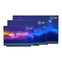
| Display Technology | QLED |
|---|---|
| Resolution | 3840 x 2160 (4K Ultra HD) |
| HDR Support | HDR10, HLG |
| Audio | Dolby Atmos |
| Connectivity | Wi-Fi, Ethernet, Bluetooth |
| Display Size | 43 inches |
| Voice Control | Sky Voice Control |
Remove the stand by placing the TV face down and unscrewing the highlighted screws (x4).
Remove 4 spacers, then use a screwdriver to remove screws (x3) and (x22) to lift and remove the rear cover.
Identify the different circuit boards including Driver, Main, T-Con, Mic, IR, and Key boards.
Remove mylar film, unplug LVDS wire, and unlock corks (x4) to release the IR board kit.
Remove tape marked in red and unplug the 10 indicated wires from the unit.
Remove foam and then unscrew (x8) the bracket found underneath the unit.
Remove specific screws (x1 yellow, x4 red) and unplug the wire to detach the Mic Board.
Remove tape and unscrew (x2) the Key Board before unplugging its wire.
Remove the specified screws (x5) to detach the Driver Board from the main unit.
Remove tape (red) by hand and separate WIFI and BT pins using a soldering iron.
Unplug FFC cables and remove highlighted screws (x10) to detach the Main Board from the unit.
Remove highlighted screws (x7) and unsolder electrolyte capacitors (x10) to detach the Power Board.
Remove mylar film (x2) by hand, then unscrew (x2) and unplug wire (x2) to remove the T-con board.