FRONT PAGE
1.
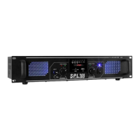
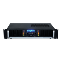
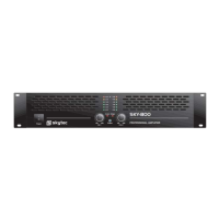
ON/OFF SWITCH WITH OPERATION LED
The LED lights up when the appliance is switched on.
2.
INPUT DAMPER
Input level attenuators reduce the level of the external signal that is looped into the amplifier's channels. The continuously
adjustable values in dB are between:
Fully closed (the signal is fully attenuated and therefore not looped into the amplifier's channels) and fully open (i.e. nominal
level.). The signal is not attenuated at all and is looped into the channels at the same level as it is present at the input).
3.
LED DISPLAY
Indicates the master output level.
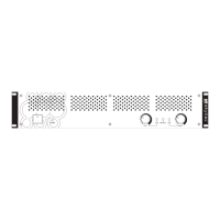
BACK SIDE
1.
LINE INPUT
Jack connector
These connectors are wired in parallel with the corresponding 6.35mm jack or RCA connectors. This allows a second device (e.g.
another amplifier) to be connected to the first one.
In this way, several amplifiers can be connected in series, all processing the same signal, forming a more powerful system.
2.
LOUDSPEAKER OUTPUT
Terminal connections and XLR connectors (minimum impedance 4 Ω).
NOTE: To avoid damage to the speaker boxes, only connect boxes that match the load and impedance of the amplifier (refer to the
amplifier's technical data). Use only speaker cables, never signal cables, i.e. those normally used for microphones, instruments and
other audio equipment.
3.
SUPPLY
Power connector.