Page 3
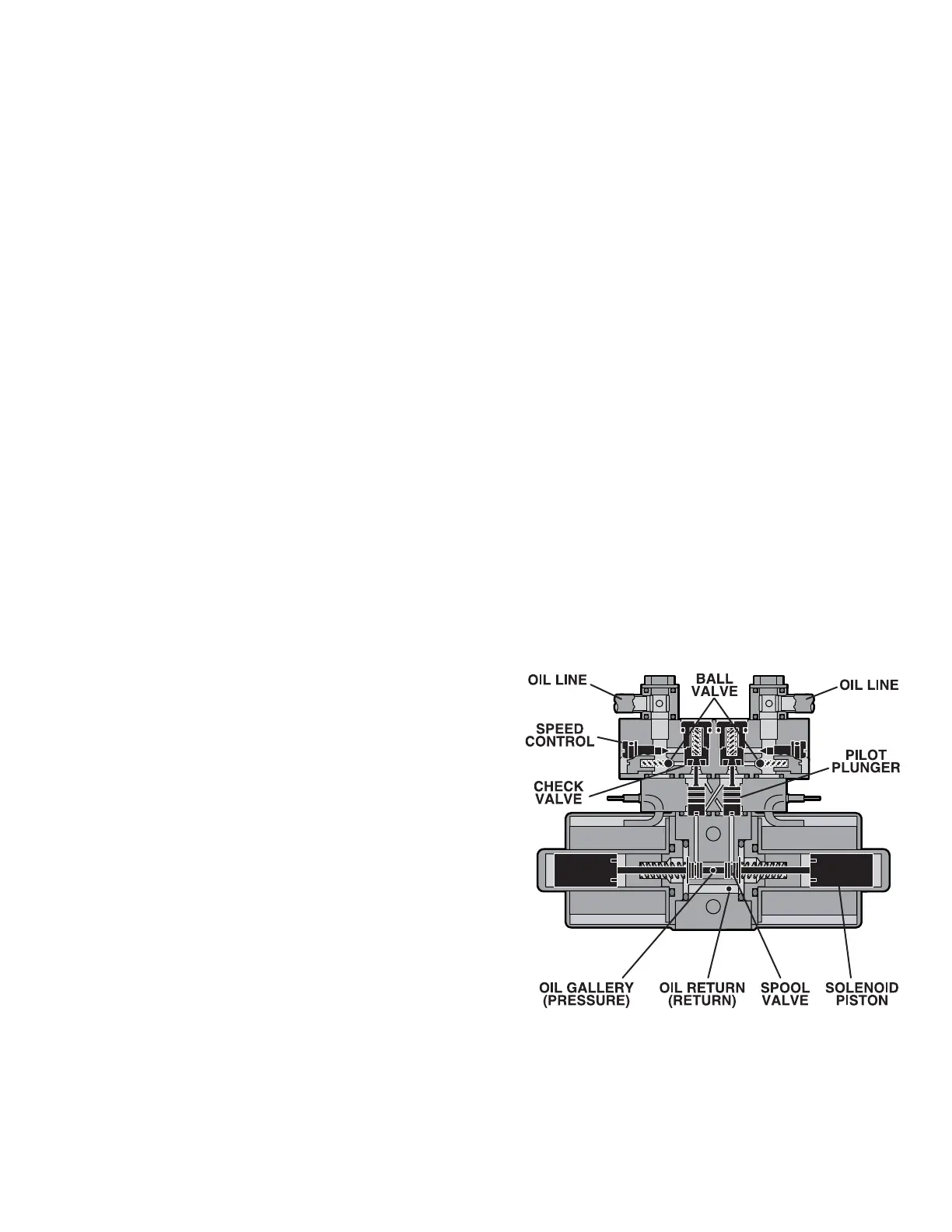
Figure 1-5. Mini-Valve in Neutral Position
c. Mini-Valves
The operation of the mini-valves is identical for all
table functions except the elevation and brake
circuits. These two hydraulic circuits use a 3-way
(single check valve) type mini-valve. All other func-
tions use a 4-way (dual check valve) type mini-
valve.
Either type mini-valve is controlled by two pushing
type, electrically operated solenoids. The sole-
noids push the spool valve (located in the lower
portion of the valve) one way or the other. This
motion opens the main supply galley (which has
pump pressure) allowing the oil to flow through the
various parts of the mini-valve to the function. The
spool valve also opens an oil return circuit which
allows the oil to return to the oil reservoir.
The main components of the mini-valve and their
functions are listed below:
1. Spool Valve - Opens the main oil galley
(pump pressure) to either mini-valve outlet de-
pending on which direction the spool valve is
pushed. Also it provides a return path for the oil
returning back into the reservoir.
2. Pilot Plunger - There are two plungers in a
four-way mini-valve (one in a 3-way mini-valve),
one under each check valve. The purpose of the
pilot plungers is to mechanically open the return
check valve allowing the oil to return back into the
reservoir.
3. Check Valve - Two are provided in each
four-way mini-valve to seal the oil in the cylinders
and oil lines and prevent any movement of the
table. One check valve is provided in a 3-way mini-
valve.
4. Speed Adjustments - There are two speed
adjustments in each mini-valve. They are needle
valve type controls which restrict the volume of oil
returning back into the reservoir, thereby control-
ling the speed of the table surface movement. A 3-
way mini-valve has only one speed adjustment.
The speed controls are always located in the return
oil circuit. This prevents uncontrolled movement of
the piston in the slave cylinder due to one side of
the piston being loaded with hydraulic pressure
and the other side having no load.
Also, by using this control method, it doesn’t matter
what size cylinder and piston is used because the
speed can be controlled by restricting the return oil.
If the pump puts out more volume to a certain slave
cylinder than the speed control is allowing to go
back to the reservoir, the pressure relief valve
provides an alternate path for the pump oil.
d. Mini-Valve in Neutral Position
(No fluid flow) See figure 1-5.
1. Spool Valve Centered - This closes off both
oil pressure and oil return galleys.
2. Pilot Plungers Both Closed -The pilot plung-
ers control the opening of the check valves. If they
are closed, the check valves must be closed.
3. Check Valves - Both check valves are
closed trapping the oil in the cylinder and oil lines.
4. Speed Adjustment - When the mini-valve is
in the neutral position, the speed adjustment does
not affect anything because there is not any oil
flow.

 Loading...


