Do you have a question about the Skytron HERCULES 6700 Series and is the answer not in the manual?
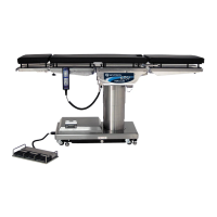
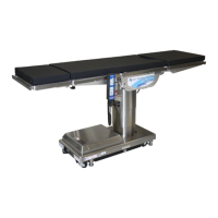
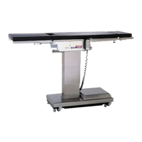
Overview of the electro-hydraulic system and its components.
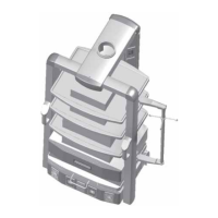
Detailed explanation of individual hydraulic system components.
Procedures for adjusting fluid level, bleeding, and pressure relief valve.
Adjusting gear mesh for the back section to eliminate lash.
Adjusting hydraulic cylinders for back and leg sections.
Adjusting the head section to eliminate flexing.
Procedure for torquing Trendelenburg tail cap bolts.
Inspecting and maintaining side rail hardware and gravity stops.
Cleaning, lubricating, and replacing table casters.
Safety precautions before troubleshooting hydraulic systems.
Guidelines for identifying and diagnosing hydraulic malfunctions.
Chart for diagnosing problems with the elevation function.
Chart for diagnosing problems with the Trendelenburg function.
Chart for diagnosing problems with the lateral tilt function.
Chart for diagnosing problems with the Flex system.
Chart for diagnosing problems with the back section function.
Chart for diagnosing problems with the leg section function.
Chart for diagnosing problems with the kidney lift function.
Chart for diagnosing problems with the brake circuit.
Guide to identifying and placing flexible hydraulic hoses.
Procedures for bleeding and adjusting the kidney lift system.
Overview of the electrical system and its functions.
Identification and relationship of electrical system components.
General information about the electrical system's operation.
General advice and approach to electrical troubleshooting.
Testing and troubleshooting the main power switch.
Testing and maintenance of the battery system.
Troubleshooting the hand-held pendant control.
Testing the capacitor, rectifier, and transformer components.
Testing and troubleshooting auxiliary switches.
Checking input power and output to the relay box.
Testing continuity of the main wire harness.
Testing solenoid coils for resistance and continuity.
Testing the motor/pump assembly and thermal protector.
Testing and identifying return-to-level and inhibit micro-switches.
General troubleshooting for return/positioning circuits.
| Brand | Skytron |
|---|---|
| Model | HERCULES 6700 Series |
| Category | Medical Equipment |
| Language | English |