Do you have a question about the Skytron HERCULES 6700B and is the answer not in the manual?
Overview of the electro-hydraulic system, its components, and power requirements.
Details the operation of key hydraulic components like the motor/pump and pressure relief valve.
Covers adjustments for fluid level, bleeding the system, pressure relief valve, and speed controls.
Procedure for adjusting the gear mesh of the back section using an eccentric cam.
Explains how to adjust hydraulic cylinders for back and leg sections to prevent twisting.
Instructions for adjusting the head section to eliminate flexing and ensure proper alignment.
Important safety precautions to follow before troubleshooting hydraulic issues.
Guidelines for diagnosing malfunctions by identifying the scope and nature of the problem.
Lists common problems and their potential causes for the table's elevation function.
Identifies common issues and reasons for improper Trendelenburg function.
Provides a diagnosis chart for problems related to the lateral tilt function.
Troubleshooting guide for issues with the Flex System, linking to back section and Trendelenburg.
Diagnoses common problems and their causes for the back section movement.
Details common problems and potential reasons for leg section malfunctions.
Lists typical problems and their causes for the kidney lift function.
Troubleshooting guide for issues with the brake system, including setting and retracting.
Guide to identifying and correctly placing flexible hydraulic hoses with number codes.
Explains the kidney lift system operation, bleeding, and cylinder adjustment procedures.
Overview of the complete electrical system, its functions, and power requirements.
Identifies and describes the key electrical components of the surgical table.
Introduction to electrical troubleshooting, covering basic operation and component impact.
Provides general guidance and notes for troubleshooting electrical system malfunctions.
Details the main power supply, its function as a circuit breaker, and testing procedures.
Explains the battery system, voltage requirements, and testing procedures for battery operation.
Describes the components for AC120V operation and provides testing procedures.
Covers the pendant control's role, troubleshooting strategies, and testing the cord.
Provides tests to determine if auxiliary switches are functioning properly.
Explains the relay box operation and provides tests for input power and output to solenoids.
Details continuity tests for the main wire harness connecting various components.
Explains solenoid function and provides resistance testing procedures for diagnosis.
Covers testing of the motor input voltage, thermal protector, and resistance.
Explains the micro-switches for return-to-level and positioning safety interlocks.
General troubleshooting steps for return/positioning circuits, focusing on micro-switches.
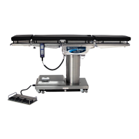
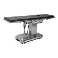
| Type | Surgical Table |
|---|---|
| Tabletop Width | 20 in (51 cm) |
| Trendelenburg | 30° |
| Reverse Trendelenburg | 30° |
| Lateral Tilt | 20° |
| Kidney Elevator | 4 in (10 cm) |
| Voltage | 120 VAC |
| Frequency | 60 Hz |
| Back Section Articulation (Up/Down) | +80° / -40° |