Page 16
SECTION II MECHANICAL TABLE ADJUSTMENTS
2-1. Back Section Gear Mesh Adjustment
The gear mesh is adjusted by the use of an ec-
centric cam. This cam moves the gear teeth closer
together to eliminate gear lash. This adjustment
arrangement compensates for any wear between
the gears that might occur.
To adjust:
Loosen the cam locking allen set screw. Use an
allen wrench to rotate the eccentric cam. See figure
2-1. Tighten the locking set screw when adjustment
is complete.
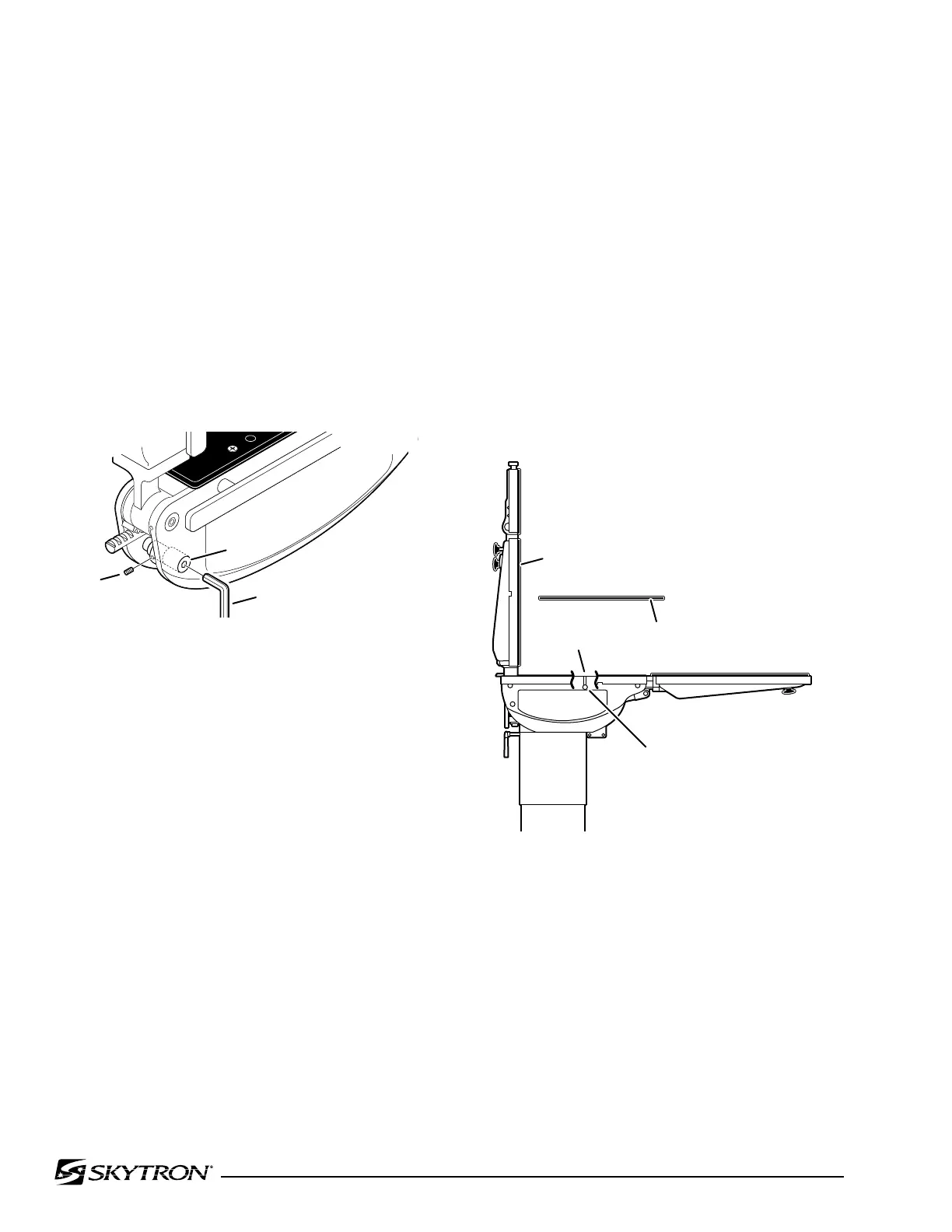
Any twisting or flexing of the back section as it ap-
proaches the stalled position indicates that one of
the cylinders is not reaching its fully extended posi-
tion at the same time as the other. This condition
would require an adjustment.
To adjust:
Remove the seat section top for access to the
cam locking set screws and loosen the set screws.
Use an allen wrench to turn the cylinder eccentric
cams as required to shift either cylinder fore or
aft as needed so no twisting or flexing of the back
section is observed when it is stalled in the full up
position. See figure 2-2. Tighten the set screws and
replace the seat section top when the adjustment
is completed.
Figure 2-1. Eccentric Cam Adjustment
2-2. Hydraulic Cylinder Adjustment
The hydraulic cylinder rams that control both the
back and foot / leg sections must move together so
that these sections are not twisted when operated.
This is accomplished by the use of eccentric cams
that move the cylinder bodies fore and aft to adjust
their effective stroke.
NOTE
Adjust gear mesh before adjusting ec-
centric cams for the back section.
a. Back Section
Position the back section all the way up until it
stalls. Both sides of the back section should stop
moving at the same time and should not show any
signs of twisting.
Figure 2-2. Back Section Adjustment
b. Leg Section
Position the leg section all the way up. Both sides
of the leg section should stop moving at the same
time and should not show any signs of twisting.
Any twisting or flexing of the leg section as it ap-
proaches the stalled position indicates that one of the
cylinders is not reaching its fully extended position
at the same time as the other and an adjustment
is required.
041905.035
ALLEN WRENCH
ECCENTRIC
CAM
SET
SCREW
041905.036
BACK SECTION
SET
SCREW
BACK SECTION
CYLINDER
ECCENTRIC CAM
SEAT SECTION
TOP

 Loading...


