Page 6
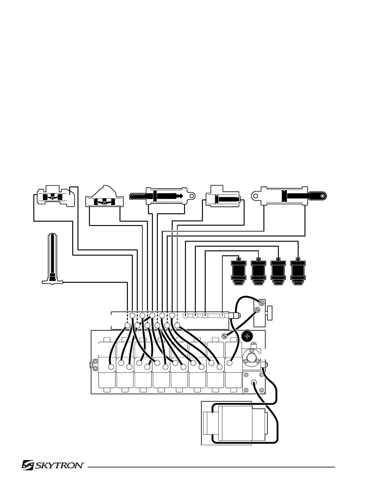
Figure 1-1. Hydraulic Block Diagram
1-1. General
Electro-Hydraulic System
The hydraulic system (with the exception of the hy-
draulic cylinders and hoses) is contained within the
base of the table. The hydraulic valves and pump
are electrically controlled by the use of a hand-held
push button pendant control. The power require-
ments for the table are 120 VAC, 5 amp, 60 Hz.
The table contains the following components. Refer
to the block diagram (figure 1-1) for relationship.
a. Oil Reservoir - Main oil supply. Approximately
two quarts.
b. Motor/Pump Assembly - A positive displace-
ment gear type pump provides the necessary oil
pressure and volume.
c. Pressure Relief Valve - Provides an alternate
oil path when the hydraulic cylinders reach the end
of their stroke.
d. Electro/Hydraulic Mini-Valve Assemblies -These
direct the fluid to the appropriate hydraulic cylin-
ders.
e. Hydraulic Lines, Fittings, Connections - They
provide a path for the hydraulic oil.
f. Hydraulic Cylinders - They convert the hydraulic
fluid pressure and volume into mechanical mo-
tion.
SECTION I HYDRAULIC SYSTEM
ELEV BRAKEKIDNEYLEGBACKFLEXTILTTREND
1
1
2
3
2
2
5
4 2
7 7 9
6 8
4 8
10
10 11
11
12
10
1 3 5
6
7 9
11
MOTOR/PUMP
ASSEMBLY
PLUMBING
TERMINAL
ELEVATION
CYLINDER
TRENDELENBURG
CYLINDER
TILT
CYLINDER
BACK SECTION
KIDNEY LIFT
LEG SECTION
PRESSURE
RELIEF VALVE
(4) BRAKE ASSEMBLIES
EMERGENCY
BRAKE RELEASE
MINI-
VALVES
3
4 5
6 7
8 9

 Loading...


