Page 10
MK SINK OWNERS MANUAL• REV4
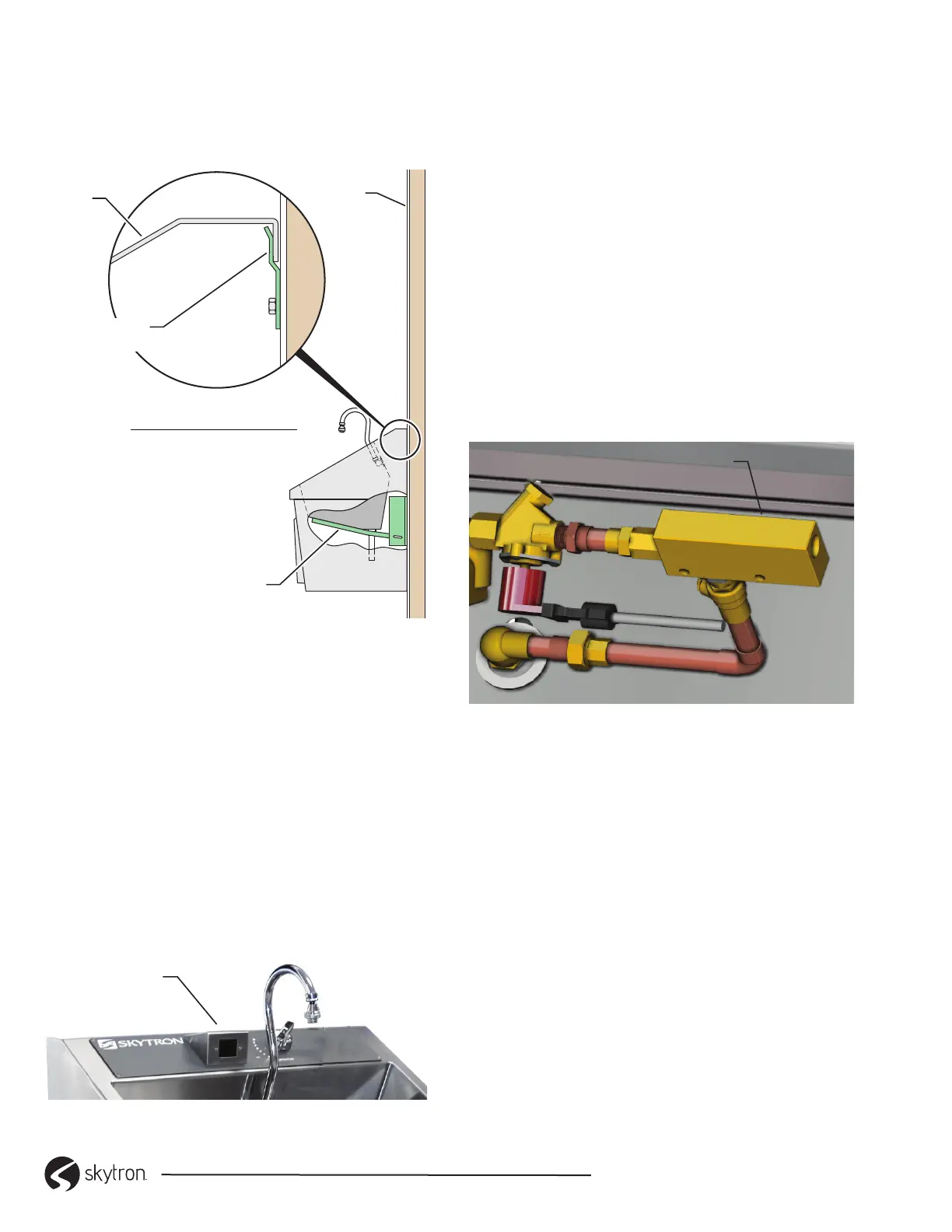
3-3. Attach Sink to Support Brackets
1. Install sink assembly on brackets making sure
the sink assembly is captured by the wall “Z”
bracket(s) (Figure 2).
WALL “Z”
BRACKET
FINISHED
WALL
TYPICAL SINK
ATTACHMENT SECTION
MAIN SUPPORT
BRACKET
SINK
Figure 2. Sink Attachment.
3-4. Infrared Controls Installation
Infrared Self-Activated Sinks are supplied with a 24V
power transformer(s) that connects to a standard
duplex outlet (110/120V outlet required).
Single basin sinks have one sensor, dual basin sinks
have two sensors (one for each basin) and triple
basin sinks have three sensors (one for each basin).
1. Plug the transformer(s) into the outlet.
2. A red LED will ash in the sensor window
(Figure 3). DO NOT interrupt the sensor beam
until the light turns o.
3.
INFRARED
SENSOR
Figure 3. Infrared Sensor
3-4-1. Sensor Initialization
The sensors are pre-set and equipped with a logic
board. The sensors determines the range during
initialization period (The time after initial power until
the light turns o is approximately 5 minutes). The
range is approximately 12-14” in front of the sensor
and is 25 degrees at peak.
During the initialization period, the sensors allow for
xed objects that may be within the sensors’ range.
The sensors are equipped with a two second on/o
delay, and no-time-out feature. This prevents the sink
from turning on when walking past at a normal pace
and no-time out allows for an uninterrupted scrub.
3-5. In-line Flow Switch Timer Controller
The in-line ow switch timer controller is available
only on Infrared Activated Scrub Sinks (Figure 4).
IN-LINE FLOW TIMER CONTROLLER
Figure 4. In-line Flow Switch Timer Controller
This is an explosion-proof brass ow switch, actuation
set point 0.50 GPM (1.89 LPM), and calibrated for
water at standard conditions. It is used for accurate
detection of excessive or insucient ow rates.
 Loading...