Page 11
MK SINK OWNERS MANUAL• REV4
CAUTION
See Switch Ratings before connecting power.
Flow settings for this switch is normally
calibrated using water @ +70°F on
increasing ow. Water calibrated units are
not recommended for air/gas applications.
3-5-4. Switch Timer Controller Maintenance
Accumulation of foreign debris should periodically
be removed from these switches. Occasional
“wipe-down” cleaning when excessive contamination
is present is all that is normally required.
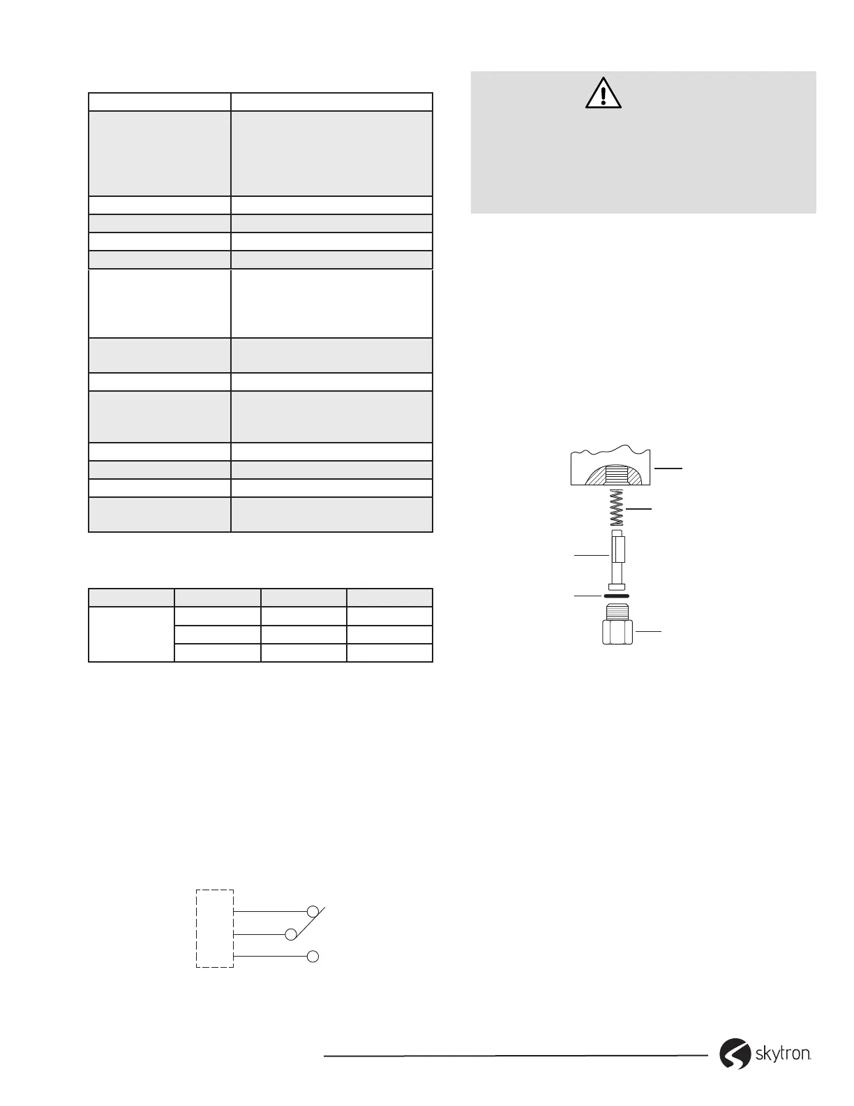
1. Remove unit from the system and disassemble
as shown (Figure 6).
2. Clean all parts. A 50 micron filter is
recommended.
3. Reassemble and reinstall unit.
PISTON
INLET FITTING
HOUSING
SPRING
O-RING
Figure 6. Switch Timer Controller
3-6. Plumbing Installation
1. Install Drain Tail Piece, Faucet and Divider if
applicable.
2. Install Optional Eye Wash Blending Valve if
applicable using instructions provided with
the valve.
3. Make all plumbing connections in accordance
with state and local codes.
4. Connect 120V, 15A power source to Infrared
Sensor Transformer if applicable.
5. Install Emergency Eye Wash sign if applicable
3-5-1. Flow Timer Controller Specications
Service Compatible Liquids
Wetted Materials Housing: Brass
Piston: polysulfone
Spring: 316SS
O-Ring: Fluoroelastomer
Other: Epoxy
Temp. Limits -20 to 225°F (-29 to 107°C)
Pressure Limits 1000 psig (68.9 bar)
Accuracy ±10% of set point
Repeatability ±1%
Electrical Rating .17 A @ 120 VAC
.08 A @ 240 VAC
.13 A @ 120 VDC
.06 A @ 240 VDC
Electrical Connection 18 AWG, 24” (60.96 cm),
Polymeric lead wires
Process Connection 1/4” female NPT
Mounting Orientation Any position. Set points shown
are based on vertical, inlet
down position.
Request Filtration 50 microns or better
Weight 0.66 lb [301 g]
Agency Approval CE
Switch Type (See
Switch Ratings)
SPDT, 20 VA
3-5-2. Switch Ratings
Switch Ratings Max Restive Load
VA Volts Amps AC Amps DC
20
0-30 0.4 0.3
120 0.17 0.13
240 0.08 0.06
3-5-3. Install the In-line Flow Timer Controller
Unit calibrated in a vertical position, with lead wires up.
1. Install unit in piping system, using standard
pipe tting procedures. Be sure to keep thread
sealing compound out of unit.
2. Make sure that ow is in proper direction -
marked “IN” and “OUT” on housing.
3. Make wiring connections according to switch
wiring diagram (Figure 5).
TYPICAL WIRING DIAGRAM
RED
BLACK
ORANGE
PIN CONNECTIONS FOR
UNITS WITH RECEPTACLE
Figure 5. Typical Switch Wiring Diagram
 Loading...