CONTROLS
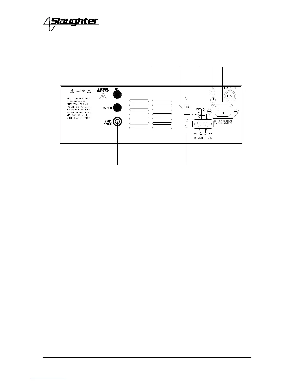
REAR PANEL CONTROLS
1. THERMAL FAN: To cool the instrument.
2. INPUT POWER SWITCH: Line voltage selection is set by the position of the
switch. In the down position, it is set for 115-volt operation, in the up position it is
set for 230-volt operation.
3. REMOTE INPUT/OUTPUT: 9-pin D subminiature male connector for remote
control of test and reset function as well as for monitoring PASS, FAIL, and
PROCESSING output relay signals.
4. CHASSIS GROUND (EARTH) TERMINAL: This safety terminal should be
connected to a good earth ground before operation.
5. INPUT POWER RECEPTACLE: Standard IEC 320 connector for connection to a
standard NEMA style line power (mains) cord.
6. FUSE RECEPTACLE: To change the fuse unplug the power (mains) cord and turn
the fuse cap counter clockwise to remove the fuse.
7. CONTINUITY CHECK OUTPUT JACK: For the connection of the detachable 5
foot (1.52 m) black return test lead. This jack is always used when performing a
continuity test. Please refer section E. Adapter Box connection for details on
connecting the adapter box between the instrument and the device under test.