10
519 6
4 2 0 21
-
MG_0326
Automatic
Main switch
5 lead Sidepower control cable
4-lead
Sidepower
controlcable
(only 3 used)
To more
control
panels
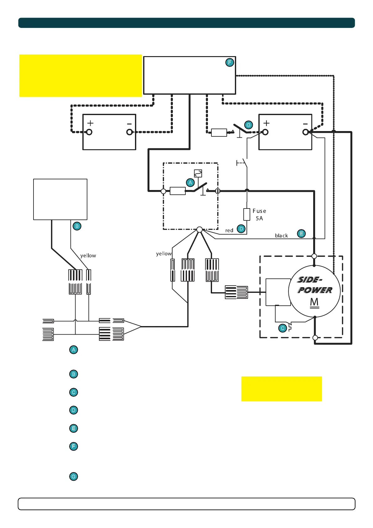
Main switch with fuse, 12 or 24V version.
(Select fuse size depending on the thruster.)
ON/OFF thruster panel(s).
Thermal switch built into the thruster motor.
Power feed fused to protect the wire.
Negative power feed for the solenoid.
Install and wire series/ parallel box that replaces the fuse and main switch between batt. 2
and the thruster with the automatic main switch.
(Dotted lines show schematically the other main cables used when fitting a
series/parallel system.)
A fuse and manual main switch fitted between battery bank 1 and the series/ parallel
switch box for shutdown in case of a fault.
( Recommended to be left on at all times to ensure charge of ”Batt. 2". Only
disconnect when installing/ servicing or in case of a failure.)
Wiring with series/ parallel
switch box installation
A
A
B
B
C
C
D
D
E
F
G
G
F
E
Control
box
Sidepower
Batt. 2
12V or 24V
Batt. 1
12V or 24V
Series/ Parallel
switch box
models are ready
with yellow output
IMPORTANT
Do NOT use an automatic main switch between
Batt 1 and Batt 2. This will prevent charging of
batt.2.
The main switch between the batteries are only for
emergencies and should be left in the ON position
except in emergencies.
IMPORTANT
Only versions 897512A and
897524A is compatible with
series/ parallel box installations
Technical Wiring Diagram