8
519 6
4 2 0 21
-
MG_0324
Battery
12V or 24V
-
Automatic
Main switch
Control
box
6 1225
black
red
SIDE-
POWER
M
Sidepower
Control panel
New ####-A
models are ready
with yellow output
yellow
yellow
5 lead Sidepower control cable
4-lead
Sidepower
controlcable
(only 3 used)
Fuse
5A
To more
control
panels
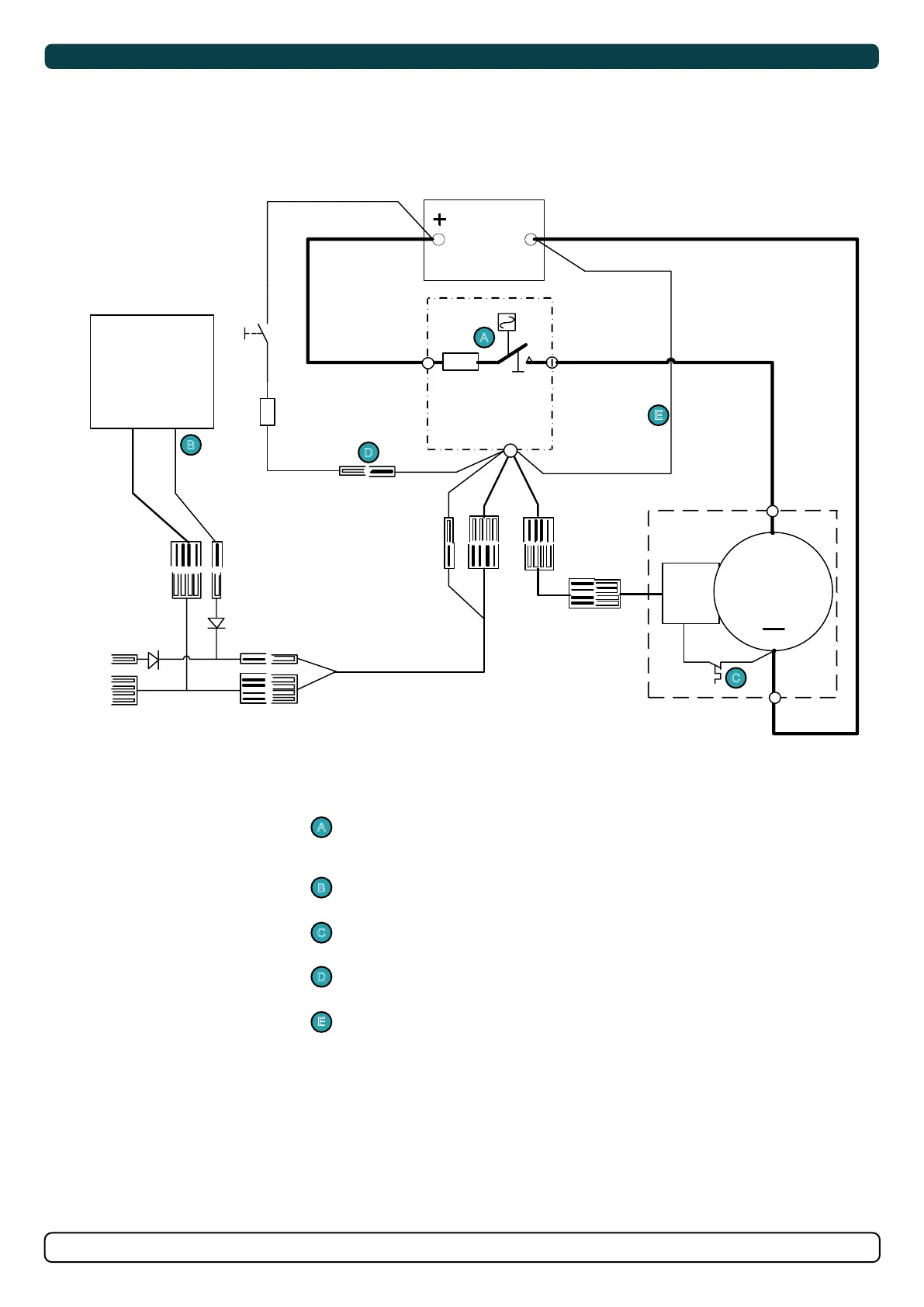
Main switch with fuse, 12 or 24V version.
(Select fuse size depending on the thruster.)
ON/OFF thruster panel(s).
Thermal switch built into the thruster motor.
Power feed fused to protect the wire.
Negative power feed for the solenoid.
Single Thruster Wiring
A
A
B
B
C
C
D
D
E
E
Technical Wiring Diagram