EasyManua.ls Logo

Slugger Magforce 06920 - User Manual

Slugger Magforce 06920
16 pages
Print Icon
To Next Page IconTo Next Page
Loading...
Slugger
®
Magforce
With Smart Magnet™ Circuitry
Slugger
®
Portable Magnetic Drilling Machine
OPERATOR’S MANUAL
HEARING PROTECTION
REQUIRED
EYE PROTECTION
REQUIRED
MODEL: #06920 (120V) OR #06921 (220V)
Serial # Date of Purchase
BEWARE OF
ROTATING
MACHINE PARTS
LINE VOLTAGE
PRESENT
NEVER PLACE
FINGERS NEAR
CUTTING AREA OR
MACHINE ARBOR
WARNING!
before use, be sure everyone using this machine reads and understands
all safety and operating instructions in this manual.
Question and Answer IconNeed help?

Do you have a question about the Slugger Magforce 06920 and is the answer not in the manual?

Summary

Important Safety Instructions

Work Area Safety

Ensures safe operation by maintaining a clean, well-lit work environment and keeping others away.

Electrical Safety Precautions

Covers proper grounding, avoiding wet conditions, and cord care to prevent electric shock.

Personal Safety Measures

Emphasizes staying alert, using PPE, and preventing accidental starts.

Safe Handling and Operation

Covers proper handling, body balance, dress code, and dust collection during operation.

Special Instructions

Cutting Area and Cutter Hazards

Avoids injury by keeping clear of cutting area, moving parts, and using proper, sharp cutters.

Grounding and Extension Cord Guidelines

Proper Grounding Instructions

Details correct grounding procedures to prevent electrical shock.

Operational Procedures

Making the Cut

Instructions for engaging the magnet, starting the motor, advancing the cutter, and maintaining pressure.

Basic Troubleshooting

Magnetic Base Performance Issues

Troubleshooting common problems with the magnetic base not holding securely.

Regular Maintenance

Overview

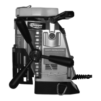
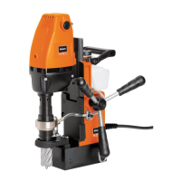
The Slugger® Magforce™ is a portable magnetic drilling machine designed for fast, efficient hole drilling in various applications. It incorporates Smart Magnet™ Circuitry, a key design feature that prevents the motor from operating under unsafe magnetic holding conditions. Illuminated on/off switches indicate the presence of a sufficient magnetic field, ensuring user safety. If these switches are not illuminated, it signifies an insufficient magnetic field, and drilling should not commence. For materials thinner than 3/8 inch, an additional steel plate may be required to achieve proper magnetic adhesion.

Technical Specifications:

  • Model Numbers: #06920 (120V) or #06921 (220V)
  • Dimensions:
    • Height: 12" (305mm)
    • Height (without coolant bottle): 11-3/8" (289mm)
    • Width: 6-1/2" (165mm)
    • Length: 11-1/2" (292mm)
  • Weight: 27 lbs. (12.25kg)
  • Motor: 1.6 HP 1200W (single phase)
    • 120V / 10.2A
    • 220V / 5.1A
    • 395 RPM (no load) - 280 RPM (load)
  • Bore: 3/4" (19.05mm)
  • Drill Point Breakaway: 1096 lbs. on 1" plate (497 Kg on 25mm Plate)
  • Magnet Base Dimensions: 4" x 6-1/2" (101.6 x 165mm)
  • Magnet Dead Lift: 1810 lbs. on 1" plate (821 kg on 25mm Plate)
  • Maximum Slugger Cutter Diameter: 1-5/8" (41mm)
  • Maximum Slugger Depth of Cut: 2" (52mm)
  • Spindle CL to Guard Face: 3-5/16" (84.2mm)
  • Spindle CL to Magnet Face: 1-3/8" (35mm)
  • Spindle CL to Motor Face: 1-3/4" (45mm)
  • Total Travel: 2-9/16" (65mm)

Usage Features:

  • Work Area Safety: Keep the work area clean and well lit. Avoid operating in explosive atmospheres. Keep children and bystanders away. Secure the workpiece using clamps or a vise.
  • Electrical Safety: Power tool plugs must match the outlet; never modify them. Avoid body contact with earthed or grounded surfaces. Do not expose power tools to rain or wet conditions. Do not abuse the power cord; keep it away from heat, oil, sharp edges, or moving parts. Use an extension cord suitable for outdoor use when operating outdoors. If operating in a damp location, use a ground fault circuit interrupter (GFCI) or residual current device (RCD) protected supply.
  • Personal Safety: Stay alert and use common sense. Do not operate while tired or under the influence of drugs, alcohol, or medication. Always wear eye protection, hearing protection, and other appropriate personal protective equipment. Prevent unintentional starting by ensuring the switch is in the "OFF" position before connecting to power or carrying the tool. Remove any adjusting keys or wrenches before turning on the power tool. Do not overreach; maintain proper footing and balance. Dress properly, avoiding loose clothing, jewelry, or long hair near moving parts. If dust extraction and collection facilities are provided, ensure they are connected and properly used.
  • Power Tool Use and Care: Do not force the power tool; use the correct tool for the application. Do not use the power tool if the switch does not turn it on and off. Disconnect the plug from the power source before making adjustments, changing accessories, or storing. Store idle power tools out of reach of children. Maintain power tools by checking for misalignment, binding, breakage, or other conditions affecting operation. Keep cutting tools sharp and clean. Use the power tool, accessories, and tools according to instructions and working conditions. Check for damaged parts before further use.
  • Assembly: The spoke handle assembly (item #30) attaches to the pinion feed shaft (item #15) using the screw attached to the center of the drive handle. The handle can be mounted on either the right or left side of the machine.
  • Before Drilling:
    1. Select the correct pilot pin and place it in the cutter shank from the rear, aligning flats on the cutter shank with arbor body set screws. Insert the cutter into the arbor body and securely tighten the set screws.
    2. Ensure the work surface is clean, flat, and free from rust, scale, dirt, and chips.
    3. Fill the coolant reservoir with a water-soluble coolant.
    4. Place the machine on the workpiece with the pilot pin over the center of the hole.
    5. Connect the machine to the power source.
    6. Lower the Slugger® cutter to the surface of the material. Coolant will be released down the pilot into the center of the cutter. Coolant flow can be stopped by lifting the pilot pin off the work surface.
    7. Securely fasten the safety strap around the workpiece and connect its ends to the D-rings on the drill. Tighten the strap to remove excess slack. The safety strap is intended to restrain the drill in case of a power failure to the magnetic base.
    8. Position the chip guard toward the work area.
  • Making the Cut:
    1. Move the magnet switch to the “I” position to engage the magnet. The red lamp will illuminate, indicating power is present and the magnet base is firmly secured.
    2. Start the drill motor by depressing the motor “I” button.
    3. Using the feed handles, advance the cutter into the material until an external groove is established. Apply smooth, constant pressure during the cut without overloading the motor. Slugger® cutters are designed for uninterrupted cutting; do not peck drill.
  • After the Cut:
    1. The "slug" or uncut center portion of the material will be expelled when the motor is returned to the full up position.
    2. Return the machine to the full upright position and depress the red motor “O” button. Wait until the motor completely stops.
    3. Move the magnet switch to the "O" position to release the magnetic base.
    4. Residual magnetism may exist after the magnet is turned off.

Maintenance Features:

  • Magnet Base: Keep the bottom of the magnet clean, free of chips, burrs, nicks, oil, and other contaminants. Inspect the magnet face to ensure it is flat and square, as a worn surface dramatically reduces magnetic holding force.
  • Quill Runout: Quill runout should not exceed .0035 inches per revolution. This is measured by placing a dial indicator needle inside the quill bore and rotating the quill. Always remove the cutter from the quill body before measuring runout. Never use hands or fingers to rotate the quill or motor spindle.
  • Motor Brushes: Inspect motor brushes and replace them as needed.
  • Parts Replacement: Replace any worn parts and regularly tighten fasteners. Never operate the machine with worn or missing parts. Use only Jancy replacement parts.
  • Magnet Test: Regularly test the machine by placing it on non-ferrous material. Engage the magnet switch; the motor should not start.

Troubleshooting:

  • Magnetic Base Not Holding Securely:
    • Material is too thin to engage the magnet.
    • Surface of material is not free of chips, debris, rust, or mill scale.
    • Size of cutter exceeds machine's rated capacity.
    • Magnet face has unevenness, nicks, or burrs.
    • Welding equipment is connected to the material being drilled.
  • Motor Slows When Drilling:
    • Extension cord is not of the recommended wire gauge or length (refer to page 6).
    • Excessive downfeed pressure during drilling.
    • Cutting tool needs to be resharpened.
  • Coolant System Not Working:
    • Machine is not in an upright position (coolant system is gravity dependent).
    • Coolant lines are blocked.
    • Dirt or debris in the coolant tank.
    • Coolant mixture is too thick.
    • Incorrect pilot pin is being used.
    • Vent hole in the coolant tank lid is blocked.
  • Slugs Not Ejecting from Cutter:
    • Lack of coolant causing slugs to expand in the cutter bore.
    • Incorrect pilot pin being used.
  • Breaking Cutters:
    • Coolant is not supplied to the interior of the cutter.
    • Excessive feed pressure applied when the cutter initially contacts the work surface.
    • Incorrect material hardness.
    • Drilling stacked materials with an incorrect cutter.
    • Dull or chipped cutting edges requiring excessive feed pressure.
  • Oversized or Rough Holes:
    • Insufficient coolant.
    • Excessive feed pressure.
    • Dull cutter.

Safety Warnings:

  • Always use eye protection.
  • Always wear hearing protection.
  • Never place hands, fingers, gloves, or clothing near the cutting area or rotating machine parts.
  • Always disconnect the machine from the power source before changing cutters, clearing chips, refilling lubricant, or performing adjustments.
  • Always use the provided safety strap and chip guard.
  • Beware of slugs ejected at the end of the cut, as they become hot.
  • Magnet will not hold properly on thin materials or rough and dirty surfaces.
  • Do not use Slugger® drilling machines on surfaces or materials being welded, as this can damage the machine's electrical components.
  • Do not operate the machine if warning and/or instruction labels are missing or damaged.
  • Position the safety guard toward the work surface before starting the drill motor.
  • If the drill motor stalls or stops before a complete cut, always shut off the motor and remove the cutter from the hole before attempting to restart. Failure to do so could result in personal injury and/or damage to the machine.

Slugger Magforce 06920 Specifications

General IconGeneral
BrandSlugger
ModelMagforce 06920
CategoryDrill
LanguageEnglish

Related product manuals