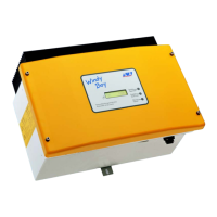
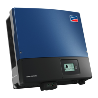
DANGER!
Electric shock caused by high voltage in the inverter.
Do not open the inverter!
The following work must be carried out by qualied personnel only.
• Electrical installation
• Repairs
• Modication
WARNING!
New safety concept!
If the Sunny Tripower beeps, the inverter has found the error and short-circuited
the PV generator. The PV system is now in a safe state.
• On no account disconnect the Electronic Solar Switch or the DC plug
connector.
• Please inform your installer immediately so that he can eliminate the error.
CAUTION!
Risk of burns through contact with the enclosure during operation.
• Only touch the lower lid and display during operation.
The inverter energy is shown as a diagram on the display. The
daily graph is displayed by default. The right-hand ashing bar
of the diagram represents the current hour. If the inverter does
not feed any power to the grid over a longer period of time (e.g.
in darkness or if the PV modules are covered with snow), a gap
is inserted into the chart. The bar for the current hour is updated
automatically every ve seconds.
After four seconds, the bar goes off for one second and then
displays the current value.
The power and energy of the inverter are displayed in three elds: Power, Day and Total. The
display is updated every ve seconds.
Power
The power that the inverter is currently feeding into the grid.
Day
The energy fed into the grid on this particular day. This equals the
energy generated between the inverter’s start-up in the morning to the
current time.
Total
The total energy which the inverter has fed into the grid during its entire
operating time.
Serial number
Identication of the inverter by the type label
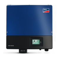
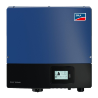
Lower enclosure lid
Graphic display
Electronic Solar Switch
LEDs
Switch open: no feeding
Switch closed: feeding
Output voltage / output current of the phase as shown below
Bluetooth connection to other devices
PV voltage/ PV current
Grid event number
PV generator event number
Inverter event number
Power reduction due to excessive temperature
• Clean the fan
• Provide better ventilation for the inverter
A
B
Phase Assignment
Switches between the inputs
A and B every 10 seconds
Green LED is on: Operation
Green LED is ashing: Waiting for sucient irradiation.
Red LED is on: Disturbance: contact installer.
Blue LED is on: The inverter has been incorporated into a Bluetooth network and can
communicate with other devices with identical NetID.
Blue LED is ashing: The inverter was identied via Sunny Explorer by setting the "Find device"
parameter.
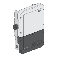
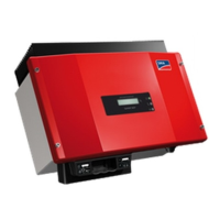
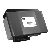
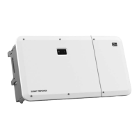
PRODUCT OVERVIEWSAFETY PRECAUTIONS
DIAGRAM POWER DISPLAY
MEASUREMENT ACCURACY
The display values may deviate from the actual values and must not be used as a basis for invoicing.
The inverter's measured values are required for the system management and to control the current to
be fed to the grid. The inverter does not have a calibrated meter.
SYSTEM OVERVIEW
LED
GRAPHIC DISPLAY
Current output
Daily energy
Total energy generated since the inverter was installed
Text line for displaying an event
Graphical display of the inverter energy/ power
The display updates the values of your PV system every 5 seconds.
Tapping on the enclosure lid:
• Activates the background illumination
• Switches from the energy values of the past 16 feed-in
hours to the daily energy values of the past 16 days
• Switches to the next text line
Disturbance:
Contact installer

 Loading...
