SB33_38-BEN104820 | IME-SB3800 | Version 2.0
PV Inverter
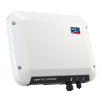
SUNNY BOY 3300/3800
User Manual
EN
ES
Symbols on the Inverter
Operation Display.
Ground fault or varistor defective.
Please inform your installer.
An error has occurred. Please inform your installer immediately.
Tap to switch on the display light and switch to the next message.
Symbols on the Type Plate
Beware of dangerous electrical voltage.
The inverter operates at high voltages. Any work on the inverter must be carried out
by qualied personnel only.
Beware of hot surface.
The inverter can become hot during operation. Avoid contact during operation.
Observe enclosed documentation.
The inverter must not be disposed of with the household waste.
Further disposal information can be found in the enclosed installation guide.
CE mark. The inverter complies with the requirements of the applicable EC
guidelines.
RAL quality mark for solar products. The inverter complies with the requirements of
the German Institute for Quality Assurance and Labeling.
Direct Current (DC)
Alternating Current (AC)
The inverter is protected against penetration by dust particles and water jets from
any angle.
The inverter has a transformer.
AC
Abbreviation for "alternating current".
DC
Abbreviation for "direct current".
Derating
A controlled reduction in performance, usually dependent on component temperatures.
Electronic Solar Switch (ESS)
The Electronic Solar Switch is part of the inverter's DC isolator. The Electronic Solar Switch must be
securely inserted into the bottom of the inverter and may only be removed by qualied personnel.
Grid impedance
Grid impedance is a characteristic parameter of the power network, which is determined by both its
infrastructure and the number of feed units and loads. If the supply for the grid section should drop
due to a grid shutdown by the preceding energy suppliers (medium-voltage transformers), the grid
impedance will change abruptly. In order to detect this and to prevent the formation of an unwanted
stand-alone grid, SMA Grid Guard monitors the grid impedance and disconnects the inverter from the
grid in the event of a sudden impedance variation.
MPP (Maximum Power Point)
Operational point of the inverter, dependent on current / voltage of the PV generator. The actual
position of the MPP changes constantly, depending on the level of solar irradiation and the cell
temperature.
PV
Abbreviation for photovoltaics.
Varistor
The varistors protect the electronics in the inverter from atmospherically coupled energy peaks, such as
those that can occur when lightning strikes nearby.
EXPLANATION OF SYMBOLS
GLOSSARY
CONTACT
If you have technical problems, rst contact your installer. The following information is required in
order to provide you with the necessary assistance:
• Inverter device type
• Inverter serial number
• Type and number of PV modules connected
• Blink code or display message of the inverter
• Optional equipment (e.g. communication devices)
SMA Solar Technology AG
Sonnenallee 1
34266 Niestetal, Germany
www.SMA.de
SMA Serviceline
Inverters: +49 561 9522 1499
Communication: +49 561 9522 2499
Fax: +49 561 9522 4699
E-mail: Serviceline@SMA.de
Installer contact
Visual inspection
Check the inverter and cables for any signs of external damage. Contact your installer if you nd any
defects. Do not carry out any repairs on your own.
Maintenance and Cleaning
Ask your installer to check for proper inverter operation at regularly.
VISUAL INSPECTION, MAINTENANCE AND CLEANING