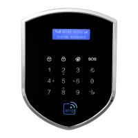
Disarm:Operation password(default 123456) + Disarm key. The light will be normally
on if the host in the disarm state
long press this button for emergency call alarm
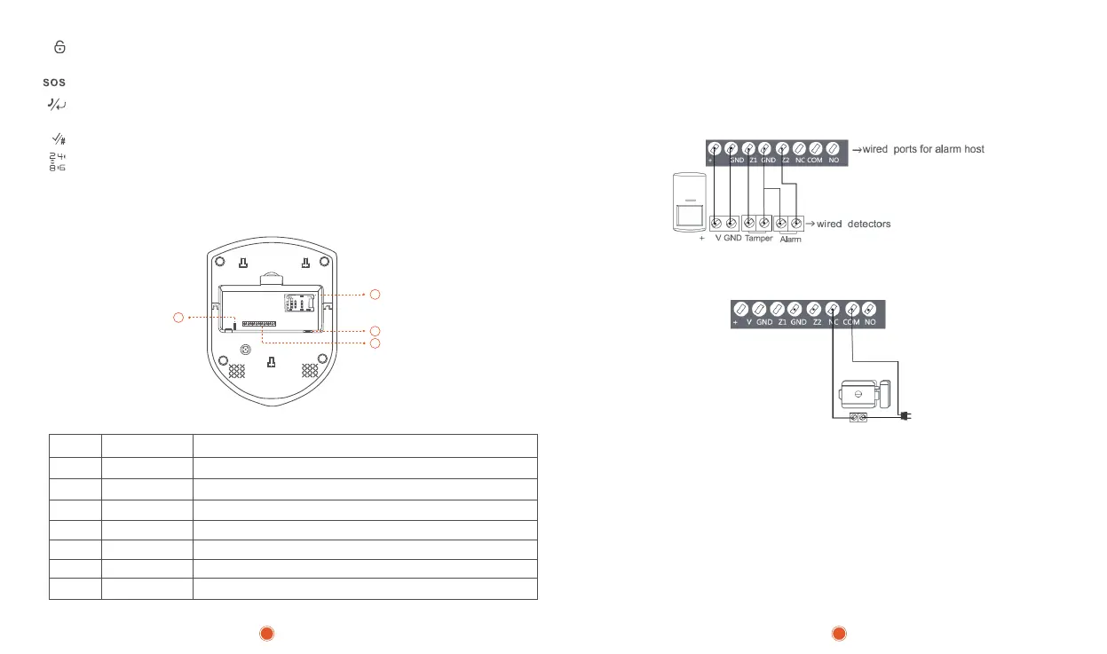
Host Function Interface Diagram:
Wired detectors connection for example,wired PIR detector with 6 ports:
Tamper output —> Z1 GND
Alarm output —> Z2 GND
+12V GND —> 5V GND
Confirm key/#
On behalf of the up\down\left\right
④RFID Card Area: in the standby mode ,short swipe card to arm the system,long swipe
the card to disarm,short card to stop the alarming when system alarme
⑤Host Function Interface Description:
⑥Host power switch
⑦SIM card slot
⑧Siren Port
Clear key/Confirm key: disarm state input telephone number,press this button to
call,press to check alarm recond
5
6
7
8
1 +5V Positive(uncontrolled)
2 GND Negative
4 GND Ground
5 Z2 Wired zone 2 input,available for both NO/NC detectors
6 NC Relay output normal closed(when closed,alarm stop)
7 COM Relay output common port
8 NO Relay output normal open(when open ,alarm stop)
3 Z1
Wired zone 1 input,available for both NO/NC detectors
Electronic control lock:Users need to connect one end of the electric lock to NC
and the other end to COM:
3 4
5V
5
5
 Loading...