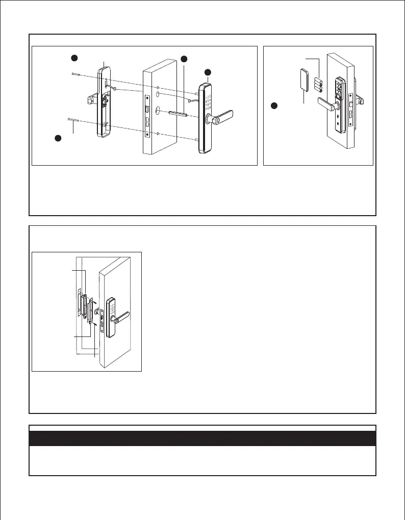
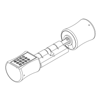
As Figure 4:
(1) Put the spindle on the mortise.
(2) Make the front panel cable across to the door plate and connect to the back
panel.
(3) fix the front panel and back panel with two screws.
As Figure 5:
(1) Put the Batteries correctly and fix the
Battery cover.
Screw
Back lock
6
4
5
Spindle
Front lock
1
Figure 4 Figure 5
3
Battery cover
Batteries
eck p.C oints after installationC6. hheck points after installation
(1)
(2) The Latch bolt,Dead bolt and Security Bolt must works smoothly and flexibly.
(3) The Front lock is vertical and stable.
The smart lock is horizontal with the door.
(1)
(2) The Latch bolt,Dead bolt and Security Bolt must works smoothly and flexibly.
(3) The Front lock is vertical and stable.
The smart lock is horizontal with the door.
As Figure 6:
(1) Install the strike box and strike plate
on the door frame with 2 screws.
(2) Test the lock if it works correctly.
Figure 6
Strike box
only)
(wood door
Strike
plate
Screw