Installation Instructions
These instructions assume the installer of this thermostat has
Knowledge of Heating & Air conditioning systems, the terminology
used in these systems and of the HVAC industry requirements.
It is an offence in Australia for unqualified persons to make any
changes to Airconditioning systems.
Failure to observe this may void equipment and thermostat
warranty, property insurance and cause irreparable damage to the
thermostat or equipment connected to it.
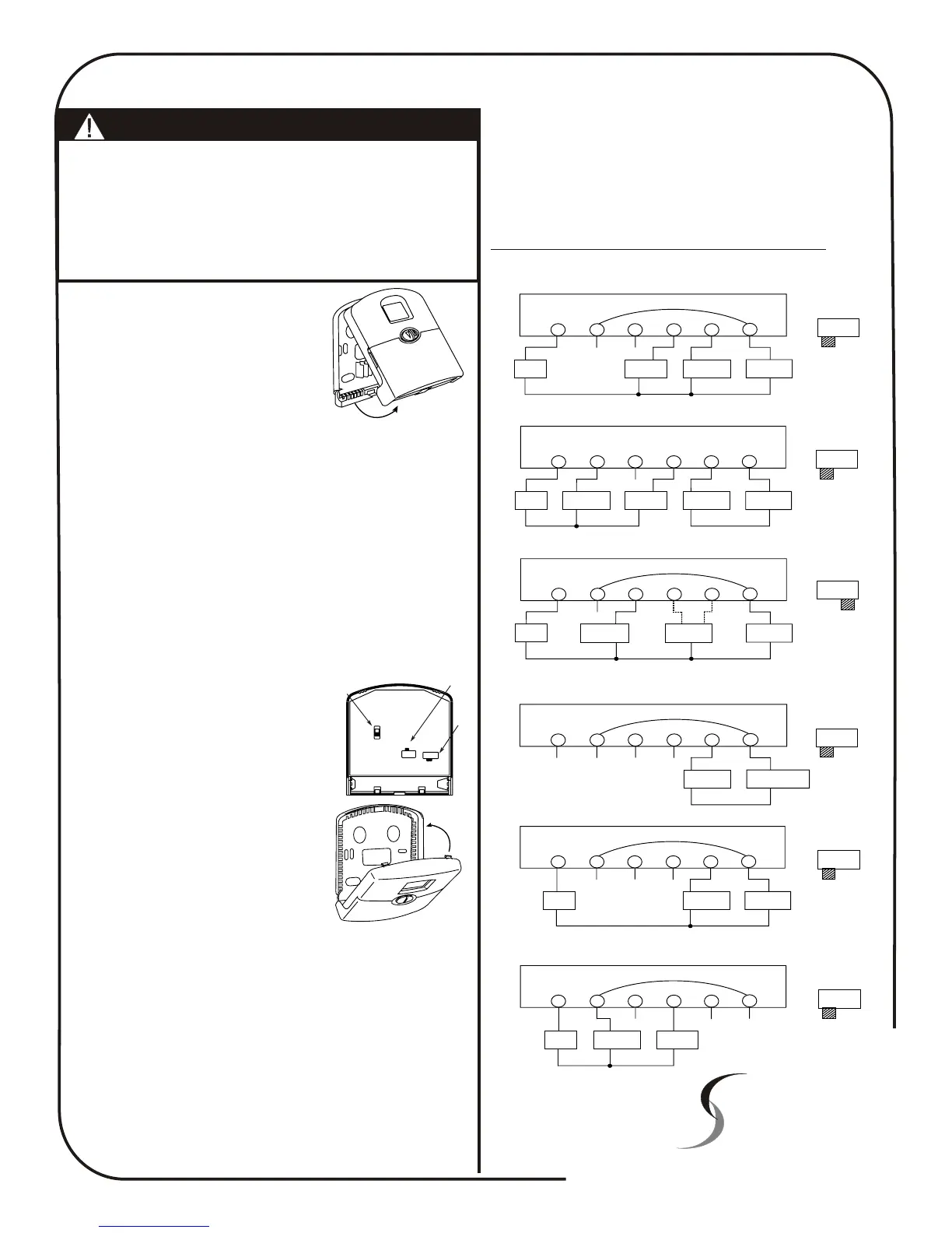
Remove the wall plate from the rear of the
thermostat by pressing the release tab
on the base of the thermostat. (Fig 8)
Position the wall plate on the wall and pull
the wires through the large opening.
Mount the wall plate with the supplied wall
anchors or other suitable means, ensure
the thermostat base is level to add to the
appearance of the installation.
Referring to the supplied wiring diagrams, connect the system
wires to the appropriate terminals on the thermostat base plate.
Ensure the screws are tightened securely to prevent potential
future problems caused by loose connections. Push excessive wire
length back into the wall cavity.
If the opening in the wall is large there may be a potential for a
draft to blow through the wall cavity and onto the temperature
sensor on the back of the thermostat. To ensure correct thermostat
operation it is important to block this hole. Failure to do so may
cause inaccurate or erratic system performance.
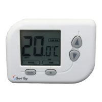
On the back of the 42-157 thermostat there are three clearly
marked selector switches. These switches are used to select the
temperature display format (deg C or deg F), the type of system
the thermostat is controlling (heat pump
or heat with add on cool) and whether the
fan is called by the thermostat (HE) or by
the system (HG)
These switch locations are shown in Fig
9. Adjust these switches to their correct
position.
Snap the two halves of the thermostat
back together taking particular care to
align the thermostat pins with the clips on
the base plate of the thermostat (Fig 10).
Set the thermostat to display the correct
time and day taking particular care with
the AM / PM and the day of the week.
Ascertain the customers requirement and
program the thermostat to the customers settings.
Test all thermostat modes by both raising the set temperature
above the ambient temperature in heat mode and verifying correct
heater operation. Next lower the set temperature to below the
ambient temperature with the thermostat in Cool mode verify the
correct operation of the equipment.
Leave a copy of these instructions for the future users of this thermostat
Should you have any questions or require any technical advice
please call Smart Temp Australia P/L on (03) 9899 6455 during
normal business hours.
Fig 8
Temperature
Display
(SW4)
Fan Option
(SW3)
System
Selector
(SW6)
C
F
HG - HE
NORM - HP
Fig 9
Fig 10
The Smart Temp 42-157 thermostat has been designed to switch 24volt
appliances only. Should you wish to control mains, 240VAC equipment
an optional Smart Pak (P/N SP - 03) interface will be required.
Please contact your place of purchase or Smart Temp Australia should
this interface be required.
The Smart Temp 42-157 is a battery powered thermostat and does NOT
require the use of a neutral. If this thermostat is replacing an existing
line powered thermostat, disregard the neutral wire.
Failure to heed this warning WILL result in thermostat damage.
X
Smart Temp
Thermostat
TM
Smart Temp Australia Pty Ltd
19 Indra Road Blackburn South 3130
Phone:(03) 9899 6455 Fax (03) 9899 6454
www.smart-temp.com.au
Y1
Y/O
W/B
Rc
G
Rh
XX
Fan
Relay
Cool
Contactor
Heat relay
or Valve
Heat / Cool
24V Supply
4 Wire Heat/Cool System
STD HP
System
Selector
Factory Installed Link
Y1
Y/O
W/B
Rc
G
Rh
X
Fan
Relay
Compressor
Contactor
Reversing
Valve
Cool
Mode
Or
Heat
Mode
Heat Pump
24V Supply
Single Stage Heat Pump
STD HP
System
Selector
Factory Installed Link
Y1
Y/O
W/B
Rc
G
Rh
XX
X
Fan
Relay
Heat
24V Supply
Heat relay
or Valve
3 wire Heat only system
STD HP
System
Selector
Factory Installed Link
Y1
Y/O
W/B
Rc
G
Rh
XX
XX
Heat relay
or Valve
Heat 24V or
Mimilivolt Supply
2 wire Heat only system
STD HP
System
Selector
Factory Installed Link
X
X
X
Y1
Y/O
W/B
Rc
G
Rh
Fan
Relay
Cool
Contactor
Cool
24V Supply
3 wire Cool only system
STD HP
System
Selector
Factory Installed Link
Y1
Y/O
W/B
Rc
G
Rh
X
Fan
Relay
Cool
Contactor
Heat relay
or Valve
Heat
24V Supply
Cool
24V Supply
5 Wire Heat/Cool System
STD HP
System
Selector
Remove Factory Installed Link
Note: