42-159 Aug-10-2011
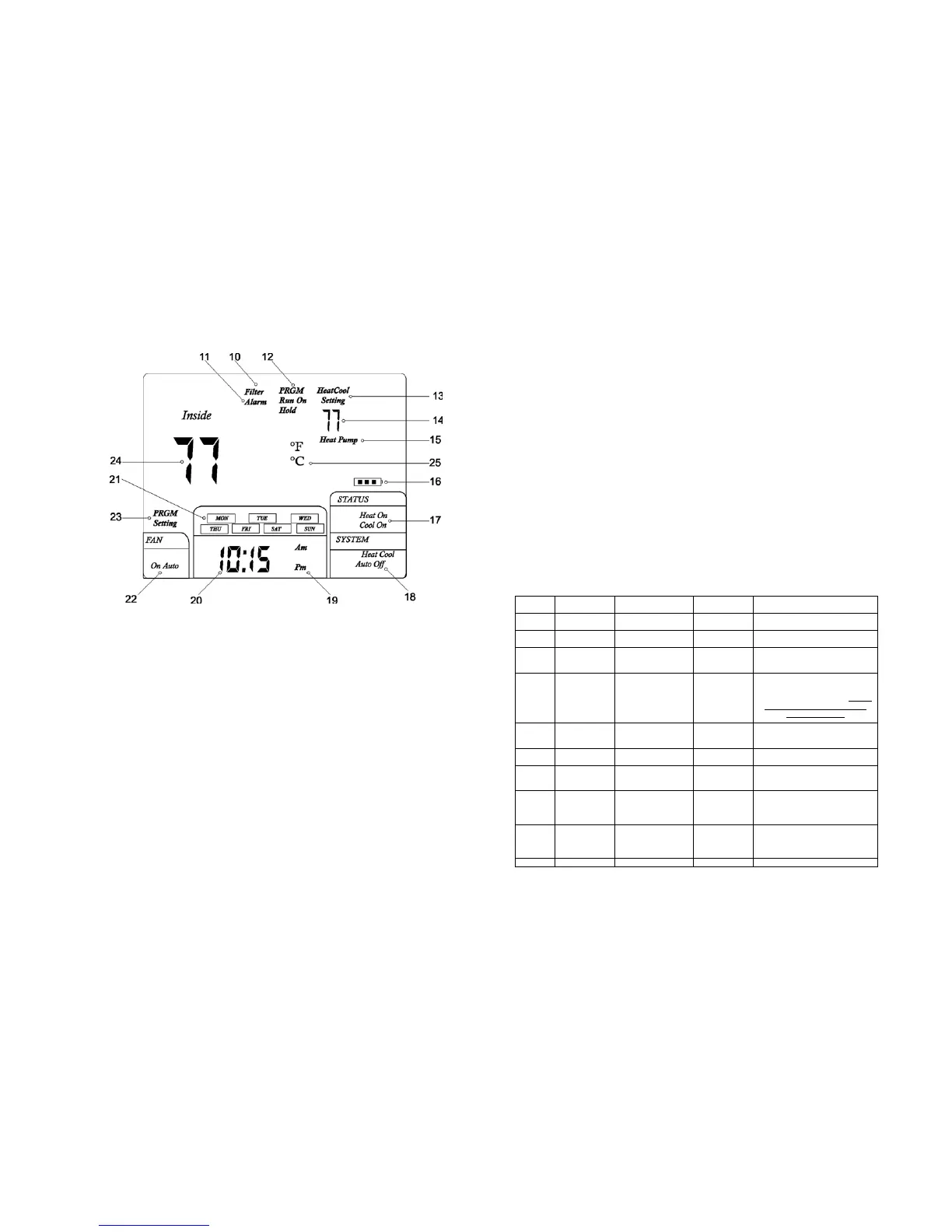
THERMOSTAT LCD DISPLAY
(10) Filter Alarm: Indicates filter needs to be replaced.
(11) Alarm: not used in this model
(12) PRGM Run On: Indicates when the thermostat is in the program RUN mode.
HOLD: Indicates when the thermostat is in the temperature HOLD mode
(13) Heat Setting: Temperature set-point in the Heating Mode
Cool Setting: Temperature set-point in the Cooling Mode
(14) Set-point temperature display
(15) Indicates thermostat is calling for heat in the HEAT PUMP mode
(16) Battery Icon: If the Battery Icon is flashing, batteries need to be replaced.
Note: It may take up to 30 seconds for the low battery icon to disappear after changing
batteries.
(17) Indicates the thermostat is calling for HEAT or COOL
(18) Indicates the current system switch position
-14-
5. It may take as long as 30 seconds for the Low Battery Icon to disappear
after changing batteries.
CAUTION!; Incorrect battery installation can damage the thermostat and void the
warranty.
CONFIGURATION AND OPERATION
1. Configuration Menu
The configuration menu allows you to set certain thermostat operating
characteristics to your system or personal requirements. Move the SYSTEM
switch to the OFF position, then press and hold the PRGM and RUN buttons for 3
seconds to enter the configuration menu. The display will show the first item in the
configuration menu. Press the PRGM button to move to the next menu item, or
press TIME to return to a previous menu item. To revert to factory default settings,
press the RESET button (See Fig. 1). All user’s changed settings will revert to
factory default settings, including program settings. Use the
▲ and ▼ buttons to
select. To exit the configuration menu and return to normal operation, press the
RUN button. If no buttons are pressed within 30 seconds, the thermostat will exit
the configuration menu.
The configuration menu chart summaries the configuration options. An
explanation of each option follows.
Step Press Buttons
Displayed (Factory
Defaults)
Press ▲ or▼
to select
Description
1
PRGM+RUN
5 seconds
CC (FA) FA or SL
Select (FA)st or (SL)ow cooling
cycles Default = FA
2 PRGM HC (FA) FA or SL
Select F(ast) or (S)low Heating cycles.
Default = FA
3 PRGM h0 (0) 0 or 1
Select system heating type, 0 = Gas,
oil, or electric heating. 1 = Heat pump
heating. Default = 0
4 PRGM bL (2) 1 – 3
Select display backlight (1) = OFF,
(2) = 30 seconds on any button
push, (3) = ON. Default = 2. Option
(3) can be activated only if the
common is used.
5 PRGM FL (00) 00, 1 thru12
Select filter time in months. Default =
00. A selection of “00” deactivates the
filter feature.
6 PRGM FC (C) F or C
Select Temperature display to indicate
°F or °C. Default = C
7 PRGM CL (0) +4 TO -4
Select temperature calibration point up
to 4° higher or 4° lower. Default = 0
8 PRGM CP (5) 0 or 5
Compressor Lockout delay. 0 = none
5 = 5 Minutes
Default = 5
9 PRGM IC 0 or 1
Intelligent Recovery Option. “1” =
Active
“0” = Deactivated.
Default = 0
10 RUN
Return to normal operation
-7-
 Loading...