Notice: if the windshield is pasted with metal thermal-protective coating or
heating coating, It may affect the receiving signal. In this case, please change
the installation place.
4.3
4.3
4.3
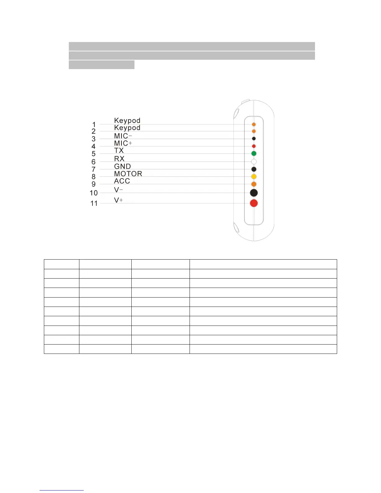
4.3 Device
Device
Device
Device outlet
outlet
outlet
outlet specification
specification
specification
specification
Line
Line
Line
Line No.
No.
No.
No. Specification
Specification
Specification
Specification Color
Color
Color
Color Instruction
Instruction
Instruction
Instruction
1. 2 Keypod Orange/ orange Connect to SOS button
3. 4 MIC-,MIC+ Black/ red Connect to Microphone
5 TX Green Sending data (TX)/backup
6 RX White Receiving data (RX)/backup
7 GND Black Ground wire
8 MOTOR Yellow Connect to relay control line
9 ACC Orange Connect to ACC ignition
10 V- Black(thick) Vehicle 12V/24V negative storage battery
11
V+ Red(thick) Vehicle 12V/24V positive storage battery
Notes
Notes
Notes
Notes of
of
of
of the
the
the
the relay
relay
relay
relay wiring
wiring
wiring
wiring
The relay wiring of pump: oil connectors of both ends are a fine white line (85)
and a fine yellow line (86). The fine white line (85) is connected to vehicle
positive power (+12V). The fine yellow line (86) is connected to the device
relay control line.
Cut off the positive connection line of the pump; then connect in series to the
relay N.C. contact (thick green line 87a) and the other end to relay COM
contact ((thick green line 30).