EasyManua.ls Logo

Smart Tracker GT06 - Device Outlet Specification; Wiring Pinout and Color Coding

Smart Tracker GT06
18 pages
Print Icon
To Next Page IconTo Next Page
To Previous Page IconTo Previous Page
Loading...
-shelter in the decorated board below the front windshield;
-shelter around the front instrument panel (non-metallic material face);
-in the decorated board below back windshield;
Notice: if the windshield is pasted with metal thermal-protective coating or
heating coating, It may affect the receiving signal. In this case, please change
the installation place.
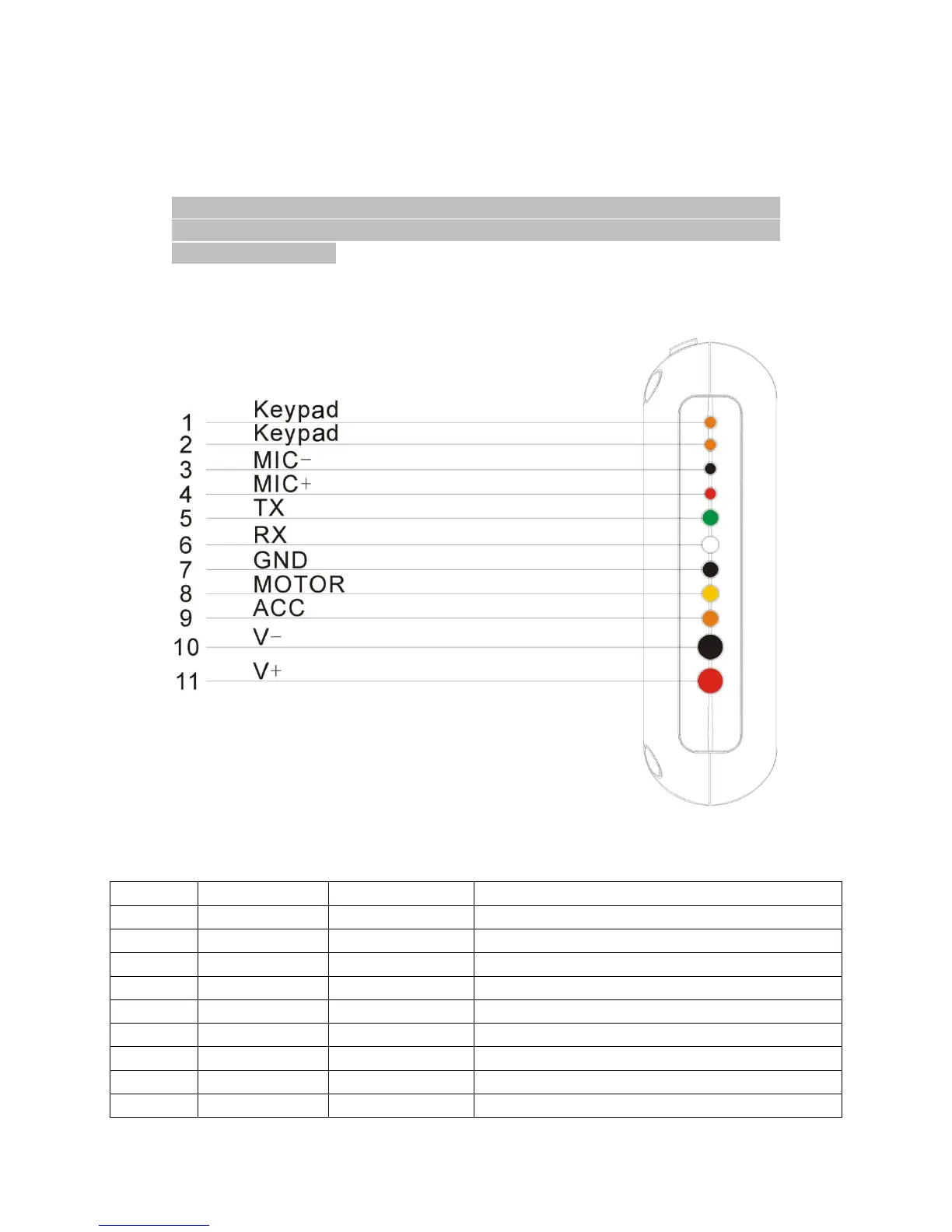
4.3 Device outlet specification
Line No.
Specification
Color
Instruction
1. 2
Keypad
Orange/ orange
Connect to SOS button
3. 4
MIC-,MIC+
Black/ red
Connect to Microphone
5
TX
Green
Sending data (TX)/backup
6
RX
White
Receiving data (RX)/backup
7
GND
Black
Ground wire
8
MOTOR
Yellow
Connect to relay control line
9
ACC
Orange
Connect to ACC ignition
10
V-
Black(thick)
Vehicle 12V/24V negative storage battery
11
V+
Red(thick)
Vehicle 12V/24V positive storage battery

Related product manuals