Complete networking
Electrical system
23
Introduction of the smart fortwo, Model Series 451
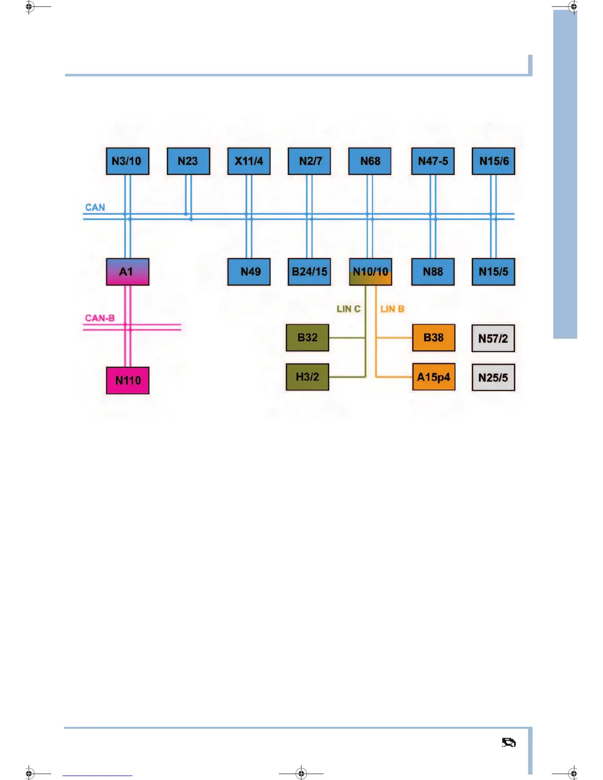
Overall network - CAN bus/LIN bus
P00.19-4339-00
Block diagram - Full equipment
N15/6 Automated manual transmission control unit
under the floor covering near the driver
seat
N23 Heater/AC operating unit
(with code (I01) Air conditioning Plus and
code (V30) Outside temperature sensor
(FFO))
in the center of the instrument panel
N25/5 Front HS [SIH] control unit
(with code (S17) Seat heaters (FFO))
in the center under the instrument panel
N47-5 ESP control unit
on ESP hydraulic unit
N49 Steering angle sensor in steering wheel
N57/2 Power window convenience feature control
unit
(with code (V43) Power windows)
on the left under the instrument panel
N68 Power steering control unit
(with code (V26) Power steering, EPS (FFO))
in interior compartment on left of firewall
N88 TPM [RDK] control unit
on left below instrument panel
N110 Weight Sensing System (WSS) control unit
on underside of passenger seat
X11/4 Data link connector
on the bottom of the instrument panel on the
driver side
CAN Controller Area Network bus
(data bus/CAN bus)
CAN-B Controller Area Network bus class B
(interior compartment)
LIN B Interior Local Interconnect Network 1
LIN C Interior Local Interconnect Network 2
SN_Typ 451_us.book Seite 23 Freitag, 30. November 2007 1:56 13