Page 5
INSTALLATION AND OPERATION MANUAL
INSTALLATION
Initial
The first step in the installation process is to deter-
mine the locations where the Status Panels will be
mounted. After this has been done, remove the 4
thumbscrews that attach the front panels to the metal
enclosures, and set the front panels aside. The metal
enclosures must be placed into cutouts in the wall
using standard practices for mounting electrical
enclosures, and an electrician must provide 120 VAC
service to the duplex outlets located inside the metal
enclosures. The current requirement is less than 1/2
Ampere per Status Panel. The box may also be
surface mounted if desired, but this does not provide
very good cosmetics and should be avoided if
possible.
When the metal enclosure is installed, the outlet box
inside the enclosure must be located to the right if
horizontally mounted or to the bottom if vertically
mounted. If this is not done properly, the panel will
not fit in the enclosure.
Configuration
The Status Panels have several options which must
be set by the installer. Setting these options consists
of turning DIP switches ON or OFF. See Figure 1 for
DIP switch details.
The first option is Master/Slave. Only ONE of the
Status Panels can be set as Master, and the others
must be set as Slaves. Setting SW1-5 down selects
Slave mode. Up is Master Mode (factory setting)
The second option is the timer for the audible alarm.
This can be set for 5 seconds or 10 seconds. Setting
SW1-4 down selects 5 seconds. Up selects 10
seconds (factory setting).
The third option is for Horizontal or Vertical mount-
ing. Setting SW1-3 down selects Vertical mounting.
Up selects Horizontal mounting (factory setting).
The fourth option is for Showmation data or RS232
data. This option is reserved for future use with other
automation systems (such as the Panalogic) or
computerized theatre information systems. Setting
SW1-2 down selects RS232 data. Up selects
Showmation data (factory setting). If you change this
factory setting, the unit will not work with the
SMART Showmations.
SW1-1 is used for factory testing but may also be
used as a field troubleshooting aid. If SW1-1 is
down, then the LEDS will light up 8 at a time and
will sequence through 12 rows and repeat. This is a
good test to see if the basic hardware is operating
properly. Up is normal mode (factory setting).
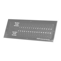
DIP Switch SW1 located
near terminal strip end of
printed circuit board
FIGURE 1
DIP Switch Up Function Down Function
SW1-1 Normal Test
SW1-2 Showmation Data RS232 Data
SW1-3 Horizontal Vertical
SW1-4 10 Second Alarm 5 Second Alarm
SW1-5 Master Slave
Power Jack