Page 6
WATCHDOG STATUS PANEL
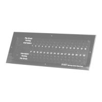
FIGURE 2
Data Cable Wiring
If the data wiring has not previously been done, then
the wiring must be run from each automation system
to the Status Panel(s). See the section on Page 7
titled Data Cable Routing and Connections for
details. See Figure 2 on this page for the location of
the Data Connection Terminals on the Watchdog
printed circuit board.
RS232 Data Conncetions
If you have ordered the Watchdog Panels for use
with a Panalogic Automation System, there will be a
separate page enclosed with this manual detailing
the connection procedures to follow for hookup.
Power Pack Connections
Connect the Power Pack plug to J1 (shown in Figure
1). Plug the Power pack into the AC outlet mounted
inside the metal enclosure.
Front Panels
If you have ordered horizontal and vertical front
panels, select the one which matches the mounting
orientation you have chosen. The Watchdog nor-
mally ships with the horizontal panels in place if
both panel types have been ordered. If vertical
mounting is desired, remove the circuit board from
the horizontal panel, and mount it on the vertical
panel.
Be careful to not overtorque the screws which
mount the pc board to the front panel as the acrylic
standoffs may be sheared off if too much torque is
applied.
Final Assembly
Dress the wires inside the metal enclosure, and
secure the front panel/pc board assembly to the
metal enclosure with the 4-40 thumb screws.
OPERATION
The Watchdog Cinema Status Panel is completely
automatic in normal operation. It is only necessary to
look at the panel to see the status in all cinemas. In the
event of a film break, the red LED will flash and the
audible alarm will sound. The alarm will stop after the
time out period (5 or 10 seconds as set up by the
installer). The LED will continue to flash until the break
has been repaired and the projector re-started. Inter-
mission is indicated by an orange LED and running by
a green LED.
Data Connection Terminals