CONFIDENTIAL AND PROPRIETARY
The Information contained in this document shall remain the sole exclusive property of s.m.s, smart microwave sensors GmbH and shall not
be disclosed by the recipient to third parties without prior consent of s.m.s, smart microwave sensors GmbH in writing.
UMRR-0C Type 42 User Manual USA-Canada_100MHz.docx Version 2 I Page 14 of 19 I November 22, 2017
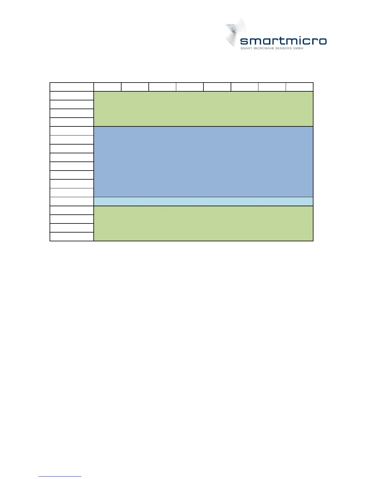
Table 3: RS485 message structure
Start sequence (4 x UINT8)
Every data message consists of its own message ID, the number of used data bytes and the
data bytes itself.
The checksum is calculated on all data except the start sequence and the end sequence. The
Checksum is a simple XOR Assignment of all n data bytes.
Byte0 XOR Byte1 XOR Byte2 ... XOR Byte (n-1)