-80-
No. DOC1045423
■EtherCAT
®
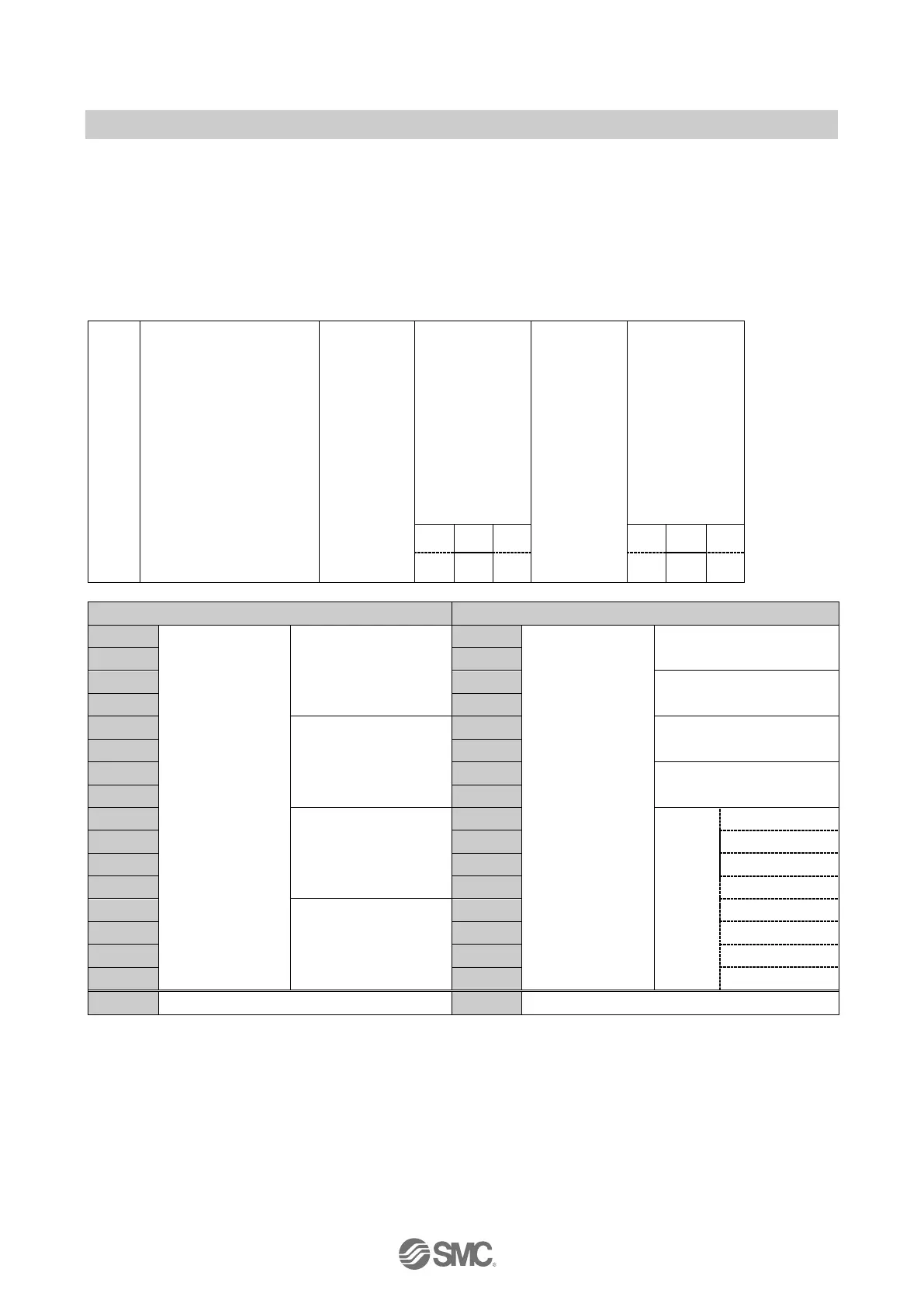
I/O Mapping example
EX600 I/O data is mapped from unit 0 in order, and when the diagnostics is valid, the diagnostic data is
mapped on top of the input data. Input/output data assigned to the SI unit on EtherCAT
®
communication is
assigned in order from the ITV module/valve on the SI unit side.
The I/O map is shown with the following unit configuration as an example.
<Example 1>
1: For details on ITV module input/output data, refer to the ITV module operation manual. (DIY-60L00-OM002)
When the “SI unit data size setting switch (ITV module)” (page 22) is set to “4 × ITV modules max.” or “2 × ITV modules max.”, the
data size of four or two ITV modules is added to the number of bytes allocated to the SI unit.
Regardless of whether there are more or fewer ITV modules actually connected, the size of the added data is the same as the size
of four or two ITV modules.
 Loading...