EasyManua.ls Logo

SMC Networks EX600-ED Series - User Manual

Default Icon
128 pages
Print Icon
To Next Page IconTo Next Page
Loading...
No. DOC1045423
PRODUCT NAME
Fieldbus system
EtherCAT
®
compatible SI Unit
MODEL / Series / Product Number
EX600-MEC1
EX600-ED#

Questions and Answers

  • R
    Randall EvansSep 10, 2025
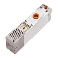
    Why is the SMC Networks Microphone system showing the red PWR(V) LED on?
    • T
      Thomas BaileySep 12, 2025
      If the red PWR(V) LED is ON on your SMC Networks Microphone system, it means the power supply voltage for output is abnormal. You should supply 24 VDC +10/-5% for the output power source.
  • K
    kimberly68Aug 23, 2025
    What to do if SMC Networks Microphone system shows abnormal valve operation?
    • A
      Ashley MackAug 23, 2025
      If you observe abnormal valve operation in your SMC Networks Microphone system, consider the following potential causes and solutions: * Check if the ladder program of PLC, etc. is correct. * Verify if the green PWR(V) LED of the SI unit is ON. If it's off, or the red LED is ON, supply 24 VDC +10/-5% to the power supply for output. * Ensure the connectors between the SI unit and manifold valve are not damaged and are correctly connected. * If the polarity of the SI unit and the valve are different, replace one of them to make the combination match. * Replace the SI unit or the valve with a normal one to check the operation.
  • B
    barbara46Aug 25, 2025
    What does it mean if the NS red LED is flashing on the SMC Networks Microphone system?
    • L
      Laura DyerAug 25, 2025
      If the red LED is flashing on your SMC Networks Microphone system, it indicates a communication timeout. This means a process active timeout has been generated. Check that the signal line is properly connected from the PLC, ensure the communication timeout interval to the EX600 is less than the set value of Process active timeout, and keep noise sources away from the communication and power supply cables. After checking these, restart the system.
  • T
    Todd HallAug 27, 2025
    What does it mean if the Red ST LED is flashing on SMC Networks Microphone system?
    • J
      James HaasAug 27, 2025
      If the Red ST LED is flashing on your SMC Networks Microphone system, it indicates a diagnosis error where the ON/OFF count of the input device has exceeded the set value. You should check the parts with error by using the LED display or PLC or H.T. Reset the ON/OFF count to zero or change the set value, or invalidate diagnosis.
  • L
    Lori MartinezAug 27, 2025
    What does it mean if the Red ST(I) LED is flashing on SMC Networks Microphone system?
    • J
      Joseph Martinez PhDAug 28, 2025
      If the Red ST(I) LED is flashing on your SMC Networks Microphone system, it indicates a diagnosis error where the ON/OFF count of the input device has exceeded the set value. You should check the parts with error by using the LED display or PLC or H.T. Reset the ON/OFF count to zero or change the set value, or invalidate diagnosis.
  • T
    Tanya BrownAug 29, 2025
    What to do if SMC Networks Microphone system shows abnormal digital output device operation?
    • B
      boyerlindsayAug 29, 2025
      If you are experiencing abnormal digital output device operation with your SMC Networks Microphone system, here are some things to check: * Ensure that the polarity (PNP, NPN) of the output unit and the output device match; replace one if they are different. * Verify that the green PWR(V) LED of the SI unit is ON. If it's off or the red LED is ON, supply 24 VDC +10/-5% to the power supply for output. * Make sure the wiring is correctly connected between the digital output device and the digital output unit. * If problems persist, try replacing the output unit or the output device with a normal one to see if that resolves the issue. * Check whether the ladder program etc. of PLC are correct.
  • R
    Ryan HallSep 18, 2025
    What does it mean if the NS red LED is ON on the SMC Networks Microphone system?
    • S
      Seth PachecoSep 18, 2025
      If the red LED is ON on your SMC Networks Microphone system, it indicates that the IP address is duplicated. Reset the IP address to one that has not been used yet.
  • J
    Jessica SanchezSep 12, 2025
    What does it mean if the Red ST(O) LED is flashing on SMC Networks Microphone system?
    • S
      sharon78Sep 12, 2025
      If the Red ST(O) LED is flashing on your SMC Networks Microphone system, it indicates that: (1) the ON/OFF count of the output device has exceeded the set value, or (2) the wire of the output device is broken or disconnected. Check the parts with error by using the LED display or PLC or H.T. For the first cause, reset the ON/OFF count to zero or change the set value, or invalidate diagnosis. For the second cause, check if the connector is loose and if the wire is broken.
  • C
    Casey FitzgeraldSep 8, 2025
    Why is the SMC Networks Microphone system showing the red PWR LED on?
    • J
      Jeremy FritzSep 8, 2025
      If the red PWR LED is ON on your SMC Networks Microphone system, it indicates that the power supply voltage for control and input is abnormal. Ensure that you are supplying 24 VDC ±10% for the control and input power source.
  • V
    Vanessa TownsendSep 5, 2025
    Why is the NS green LED flashing on the SMC Networks Microphone system?
    • D
      Dean KingSep 5, 2025
      If the NS green LED is flashing on your SMC Networks Microphone system, it indicates that communication is not established. Check that the signal line is connected from the PLC, the communication speed of PLC and SI unit is appropriate, and the communication line is wired away from any noise source. After checking these, restart the system.

Summary

Safety and Handling Instructions

General Safety Guidelines

Explains hazard levels (Danger, Warning, Caution) and general safety rules.

Product Handling Precautions

Covers installation, wiring, and environmental considerations for safe product use.

System Overview and Configuration

System Configuration and Components

Describes the EX600 system range, units, and their functions.

Definitions and Terminology

Provides definitions for key terms used in the manual.

Assembly and Mounting Procedures

Unit Assembly and Manifold Composition

Details on connecting units and composing them into a manifold.

Direct Mounting Procedures

Explains the procedure for direct mounting of the unit.

DIN Rail Mounting Procedures

Explains the procedure for mounting the unit on a DIN rail.

Mounting the Marker

Explains how to install markers for unit identification.

Component Configuration Details

SI Unit Model, Parts, and Wiring

Covers SI Unit model indication, product parts, and wiring information.

SI Unit Switch Setting and LED Indicators

Details switch setting operations and LED indicator functions for the SI Unit.

End Plate Model, Parts, and Wiring

Covers End Plate model indication, product parts, and wiring.

End Plate Power Supply Types

Explains the two types of power supply systems used with the end plate.

Product Specifications and Dimensions

Product Specifications

Lists technical specifications for communication, electrical, and environmental conditions.

Physical Dimensions

Provides detailed physical dimensions of the unit.

Troubleshooting and Maintenance Procedures

Maintenance Procedures

Details on cleaning, inspection, and resetting the product.

Troubleshooting Guide

Provides a flowchart for identifying and resolving system failures.

Trouble Countermeasure Methods

Lists specific problems, presumed causes, and troubleshooting steps.

Parameter Configuration Guide

System Parameters

Details settable parameters for the system, SI unit, and ITV module.

SI Unit Parameters

Covers parameters for SI units related to valve and ITV control.

Digital I;O Unit Parameters

Details parameters for digital input, output, and I/O units.

Analogue Unit Parameters

Details parameters for analogue input, output, and I/O units.

Other Unit Parameters

Covers parameters for frequency, temperature, and IO-Link master units.

Parameter Data Details

Provides detailed lists of parameter data for SI units.

I;O Mapping and Diagnostics

I;O Map and Byte Allocation

Details allocated input/output bytes for each unit type.

IO-Link Master I;O Map and Diagnostics

Explains IO-Link master I/O map details and port status diagnostics.

EtherCAT I;O Mapping Examples

Illustrates I/O mapping with practical examples.

Diagnostic Data Details

Provides a detailed breakdown of diagnostic content.

Hardware and Software Configuration

Hardware Configuration (ESI File)

Information on ESI file installation and TwinCAT setup.

CoE Object Dictionary Usage

Guide on using the CoE object dictionary for parameter access.

Network Configuration and Web Server Access

IP Address Setting (EoE)

Instructions for setting the IP address using EoE.

Web Server Operation and Monitoring

Overview of the web server and how to connect and monitor the unit.

Available Accessories

Mounting Hardware and Connectors

Lists valve plates, brackets, and connectors for mounting.

Cables

Lists various EtherCAT, IO-Link, and power supply cables.

SMC Networks EX600-ED Series Specifications

General IconGeneral
Rod MaterialStainless Steel
Protection ClassIP67
SeriesEX600-ED Series
Operating Temperature Range-10 to 60 °C
Port SizeM5, Rc1/8
Maximum Speed500 mm/s
Body MaterialAluminum

Related product manuals