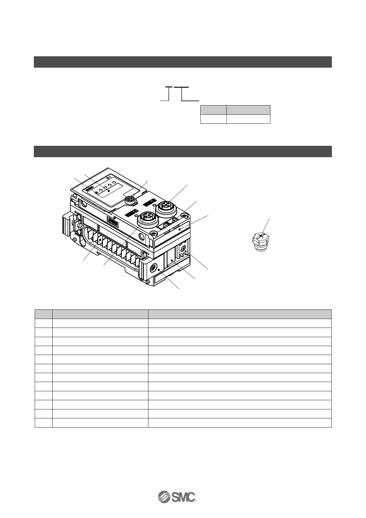
EasyManuals Logo
Home>SMC Networks>Industrial Equipment>EX600-ED Series

SMC Networks EX600-ED Series User Manual

Default Icon
128 pages
To Next Page IconTo Next Page
To Previous Page IconTo Previous Page
Page #17 background imageLoading...
Page #17 background image
-17-
No. DOC1045423
SI Unit
Model Indication and How to Order
EX600-MEC1
SI unit for 64-station
compatible manifold
Protocol
Symbol
Content
EC
EtherCAT
®
Summary of Product parts
No.
Description
Function
1
Status display LED
Displays the status of the unit.
2
Display cover
Open when making the switch settings.
3
Display cover screw
Loosen the screw to open the display cover.
4
BUS OUT connector (PORT 2)
Connection for the fieldbus communication cable.
5
Marker groove
Groove for an identification marker.
6
Valve plate mounting screw hole
Holes for mounting the valve plate.
7
Valve plate mounting groove
Groove to insert the valve plate.
8
Joint bracket
Bracket for joining to adjacent units.
9
Unit connector (plug)
Connector for transmitting signals and power to adjacent units.
10
BUS IN connector (PORT 1)
Connection for the fieldbus communication cable.
11
MAC address label
Displays the 12-digit MAC address which is different for each SI unit.
12
Seal cap
Fit to unused connectors. Factory installed on PORT2.

Questions and Answers:

Question and Answer IconNeed help?

Do you have a question about the SMC Networks EX600-ED Series and is the answer not in the manual?

SMC Networks EX600-ED Series Specifications

General IconGeneral
BrandSMC Networks
ModelEX600-ED Series
CategoryIndustrial Equipment
LanguageEnglish

Related product manuals