INTRODUCTION
The PME-500-TR integrates measurement instruments and a number of test automation devices in a single piece
of equipment designed for the evaluation and condition assessment of three-phase circuit breakers. This
document describes a few simple procedures to ensure the correct operation of all the functions involved in the
evaluation of a circuit breaker without doing an actual test. These procedures may help the user diagnose
common problems quickly and, in most cases, provide a permanent solution with no need to return the
equipment to a service centre. Measurement accuracy, however, falls beyond the scope of this guide, as it
requires specific resources, knowledge, and environmental conditions only guaranteed by EuroSMC and
authorized calibration laboratories.
We recommend you to conduct the following tests before contacting EuroSMC or your local service
representative if you face trouble while using your PME-500-TR.
Checking the coil control system
The coil control system consists basically of two solid-state on/off switches opening or closing the circuit that
supplies power to the circuit breaker’s operation coils. These ‘switches’ are sensitive to polarity, and can be
operated manually by pressing the ‘open’ or ‘close’ buttons in the PME-500-TR’s TEST menu. To check the
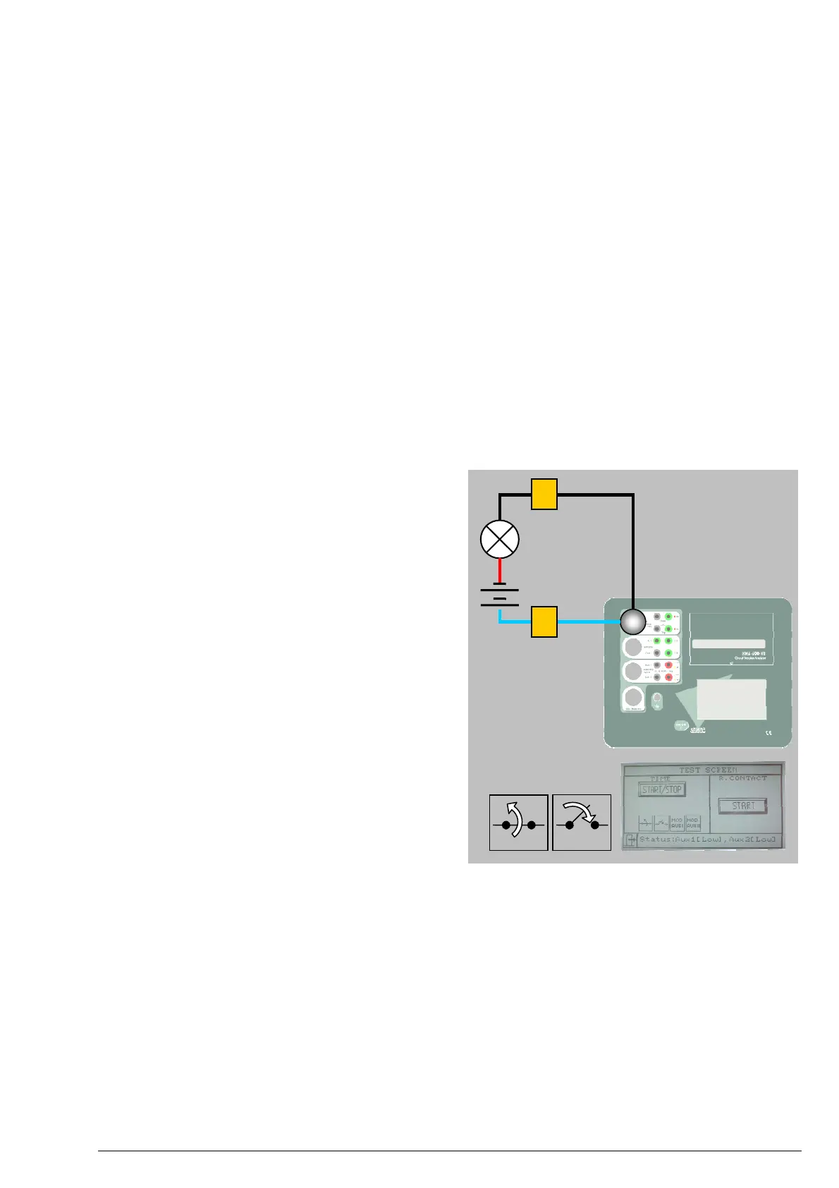
coil control system for proper operation, you will need a small lamp, a suitable battery, a short section of
conductor and a few simple steps:
1. Plug the coil control cable (black / blue leads
labelled “C” and “T”) into the Coil Control
multi-connector.
C
2. Open the SET menu and set Duration to 1000
ms. for both Close and Open.
C
3. Connect the terminal labelled as “C” at the end
of one of the blue leads to the battery’s positive.
4. Connect the other terminal labelled as “C”
(black lead) to one pole of the lamp.
5. Complete the circuit by connecting the other
pole of the lamp to the battery’s negative with
your section of conductor. The lamp should
NOT be lit.
6. Open the TEST menu and press the Manual
Close button while observing the red On LED
on the right of the black/green Close connectors.
This LED and the connected lamp should be
simultaneously lit for one second.
OPEN CLOSE
7. Repeat steps 2-6, this time using the “T”
terminals and pressing the Manual Open button while observing the red On LED on the right of the
black/green Open connectors.
If you obtain different results check your cables for continuity and refer to the troubleshooting guide in the
user’s manual. There are internal fuses that might be blown.
Checking the main contact state detection
The PME-500-TR determines the state (open or closed) of the circuit breaker’s contacts by measuring the
resistance between both sides. You can easily check your unit for proper recognition of open or close states by
following these steps:
1. Plug the main contact timing cable into the Contacts multi-connector. This lead groups six leads with
black / red 4-mm terminal pairs labelled C1, C2, and C3 respectively.
©EuroSMC, S.A. 2005 – PME-500-TR Basic Performance Test Procedures Page 2 of 4
 Loading...