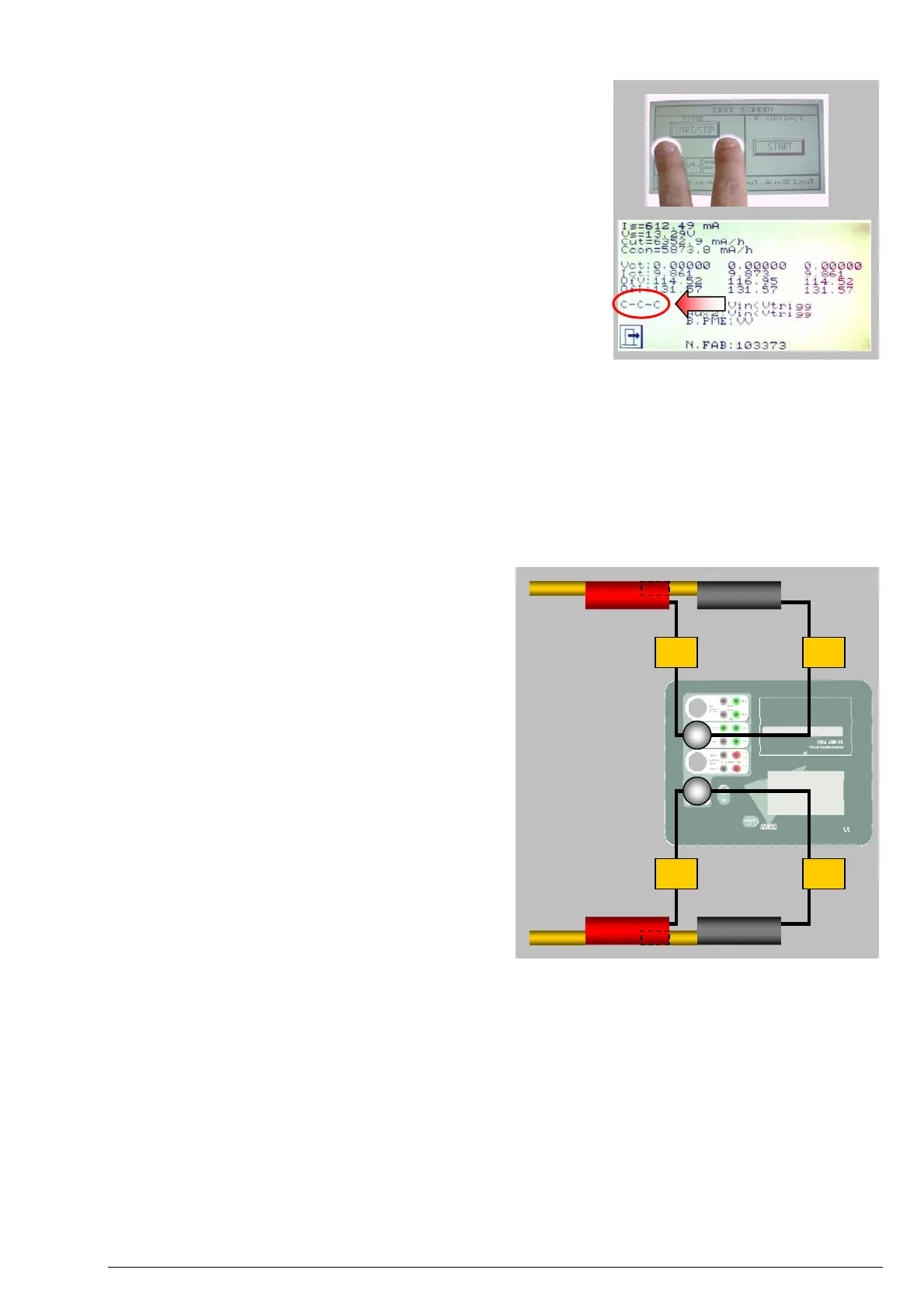
2. Open the TEST screen and touch underneath the two lower
corners of the START/STOP button. The Factory
Measurements screen should be displayed. The signature “O-
O-O” should be visible on the lower left, indicating that C1,
C2 and C3 pairs are disconnected (Open).
3. Interconnect the black and red terminals labelled as C1. The
signature should change to “C-O-O” after a short while. Do
not undo the connection yet.
4. After doing the same with the C2 terminals, the signature
should change to “C-C-O”
5. Finish with the C3 terminals to display “C-C-C” and then undo
the three connections successively while observing the display
as it returns to “O-O-O”
If you obtain different results, check your test leads for continuity and
refer to the troubleshooting guide in the user’s manual. There are internal fuses that might be blown.
Checking the contact resistance measurement
The PME-500-TR uses the four-wire method (Kelvin connection) to measure the resistance of the three closed
poles in the circuit breaker. This is the simplest way to check the integrity of the resistance measurement system
for the three phases:
1. Ensure that the PME-500-TR’s battery holds some charge or leave the unit switched off and connected
to an AC outlet to re-charge for at least 15 minutes. This test takes the power from the battery, even if
the unit is connected to a mains AC outlet.
C1
2. Plug the main contact timing cable into the
Contact multi-connector in the PME-500-TR
(you may have it already connected after
performing the procedure above)
C1
3. Plug the voltage measurement cable into the
Res. Measure multi-connector.
4. Interconnect the black and red terminals labelled
as C1 at the free end of the Contact timing cable
as shown in the figure.
5. Do the same with pairs C2 and C3
6. Do the same with pairs R1, R2, and R3 at the
free end of the Res. Measure cable.
R1 R1
7. Open the TEST menu and press the START
button on the right. The PME-500-TR will
measure the contact resistance of the three
‘poles’ and a “Test finished” message should be
displayed after a short while.
8. Exit the TEST menu and navigate the RES tab for the measured resistance values. The three values
should be exactly ZERO.
If you obtain different results, check the continuity of your test leads, double-check the connections as described
above and repeat the test. If problems persist, refer to the troubleshooting section in the user’s manual. There are
internal fuses that might be blown.
Checking the Auxiliary inputs
The Aux1 and Aux2 inputs can be used individually as timing inputs for other contacts in the circuit breaker
(typically the coil or the signalling contacts) or as triggering inputs to synchronize the PME-500-TR to an
external start signal when a remotely controlled test is required. To check these inputs for integrity and proper
operation, do the following:
©EuroSMC, S.A. 2005 – PME-500-TR Basic Performance Test Procedures Page 3 of 4
 Loading...