8. Connect the low voltage output cable from the power supply unit by inserting the mini-
DIN plug into the socket at the rear of the base. Take care to see that it is pushed fully
home. Connect earth wire from PSU to the motor earth stud. An on-off switch is situated
on the back of the power supply unit.
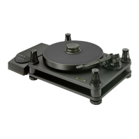
13. Fitting the Model 10 Precision Pick-up Arm
1. Unpack and check all items against the packing list on page 7. In the unlikely event that
something is missing notify your dealer and SME Limited immediately.
2. The heads of the base clamp bolts are presented to the rear of the tone-arm for ease of
access. Using the 3mm A/F ball-ended wrench, see that both are lightly locked and then
released by three-quarters of a turn only. This will enable the pillar to be moved vertically
in the base. The clamp bolts must not be re-locked until installation and adjustments have
been completed. The movement is internally spring loaded so settings will not be lost in
the meantime.
3. Remove the four socket cap screws M3 x 12 from the Model 10 sub-chassis (Arm
Mounting). These have been provided in case you should wish to use another model from
the wide range of SME precision pick-up arms.
4. Position the arm on the sub-chassis, engage the small location pins protruding from the
underside of the arm base into the narrow slot in the sub-chassis. Fit a washer to each of
the M4 x 18 socket cap screws and insert them from under the sub-chassis through the
slots on either side and screwing them up into the tapped holes in the arm base. Position
the turntable so that the sub-chassis overhangs the edge of the table allowing the cap
screws to be tightened with the ball-ended hexagon wrench 3mm A/F and then released
by three-quarters to one turn to allow for arm adjustment.
5. Plug in the audio lead. The socket at the bottom of the arm pillar rotates through 315
degrees allowing a wide choice of position.
The ground lead serving the arm should be connected to the ground terminal of the pre-
amp and those from the phono plugs to the ground terminal on the piece of equipment to
which the plugs are connected, ie. transformer, head-amp of pre-amp.The system has been
designed for a high signal to noise ratio and if this is not achieved, multiple ground paths
or the over proximity of mains equipment will be likely causes.
WARNING! To prevent bridging the compliance of the turntable’s suspension, the audio lead
and the low voltage cable from the power supply must be routed clear of the turntable base and
the surface on which the turntable is mounted. Failure to do this can result in acoustic feeback.
14. Fitting the Cartridge
1. Before fitting the cartridge see that its stylus guard is in position as a precaution against
accidental damage.
LCOFC cartridge leads have 1mm diameter receptacles for the headshell and standard
1.25mm for the cartridge. The latter may require adjustment with pliers or a screwdriver
blade for a snug fit on non-standard terminals.
Connections to the cartridge must never be made by direct soldering.