8. UNPACKING
1. Unpack and check all items against the packing list on Page 7. Any missing parts should
be reported to your dealer at once.
2. The turntable should be placed on a substantial table or steel equipment stand, this should
be in its final position for setting up, as movement after this procedure is best avoided.
3. The levelling feet allow for two methods of interface with the mounting surface.
a) As received on rubber insert pads set into the underside of the feet.`
b) Stainless steel balls also set into the underside of the feet.
WARNING:
Method (b) is not suitable for delicate surfaces as indentation may be caused.
4. If hard mounting the turntable on the stainless steel balls is preferred, proceed as follows:
a) Position the base so that one end overhangs the table by about 10cms, unscrew and
remove both of the exposed feet.
b) Remove the rubber pad from the foot by pushing out through the small hole on the
upper side of the foot using the longer leg of the 2mm A/F hexagon wrench.
c) Replace the turntable feet and repeat the procedure for the two feet at the opposite end
of the unit.
5. Lift the left hand end of the turntable and remove the Motor Transit Screw from the
underside of the base immediately below the motor. Remove the Motor Retaining Band.
Remove the two packing strips from beneath the motor and relocate the three motor feet in
the dimpled mountings. Refit the Motor Retaining Band.
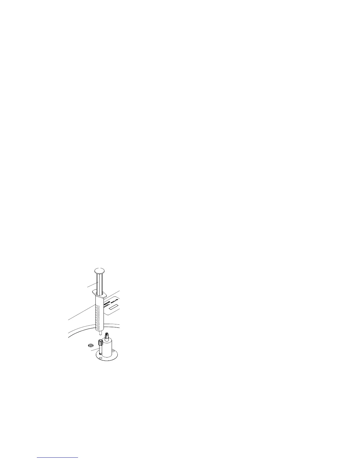
6. The turntable is packed with only a little oil in the bearing housing and this should now be
filled. A metered charge is provided in Syringe Part No: 1058/20.
7. Remove the syringe from its packing and insert the tip into the
Oil Filler Adaptor, which will be found already fitted to near
the spindle. (as illustration left).
8. Slowly inject the complete quantity into the bearing
maintaining downward pressure throughout the operation to
prevent leakage.
9. Remove the syringe and dispose of it responsibly!
10. Unscrew and remove the Oil Filler Adaptor using the Box
Spanner Part No: 1946. Retain the adaptor for possible future
use
11. The suspension is also secured for transit and the two screws
are accessible through holes in the driven pulley (see page 8, suspension transit screws). Hold
the sub-chassis down and remove these screws with their sleeves using the 4mm A/F hexagon
wrench, allow the chassis to rise under the natural pull of the suspension.
Syringe of
Spindle Oil
Oil Filler
Adaptor
9
 Loading...