Instructions for the installer
20
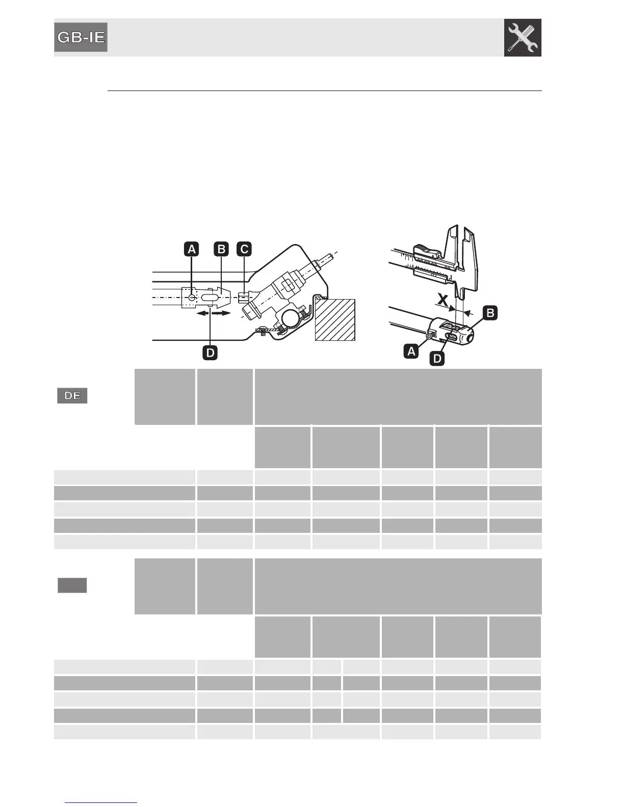
9.2 Adjustment for LPG
Loosen screw A and push support B all the way. Using a a double head, remove
nozzle C and replace it with the appropriate nozzle, following the instructions in the
tables for the type of gas to be used. The nozzle tightening torque must be no more
than 3 Nm. Reposition support B so that nozzle C is covered perfectly.
Move the Venturi tube D to adjust the air flow until distance “X” is reached indicated
in the chart in paragraph "5.5 Primary air adjustment” and then secure the tube by
means of screw A. After the adjustments have been carried out, restore the seals
with sealing wax or equivalent material.
Burner
Rated
heating
capacity
(kW)
LPG – G30/G31 50 mbar
Nozzle
diameter
1/100 mm
Bypass
mm
1/100
Reduced
capacity
(W)
Capacity
g/h G30
Capacity
g/h G31
Auxiliary (1) 1.05 42 26 380 76 75
Semi-rapid (2) 1.65 54 26 380 120 118
Rapid (3) 2.55 67 33 650 185 182
Rapid (4) 3.1 73 37 750 225 222
Ultra-rapid (5) 3.9 82 55 1600 283 279
Burner
Rated
heating
capacity
(kW)
LPG – G30/G31 28/37 mbar
Nozzle
diameter
1/100 mm
Bypass
mm
1/100
Reduced
capacity
(W)
Capacity
g/h G30
Capacity
g/h G31
Auxiliary (1) 1.05 48 30 33 (*) 380 76 75
Semi-rapid (2) 1.65 62 30 33 (*) 380 120 118
Rapid (3) 2.55 76 37 40 (*) 650 185 182
Rapid (4) 3.1 85 43 45 (*) 750 225 222
Ultra-rapid (5) 3.9 95 65 1600 283 279
(*) By-pass value for appliances without valves.