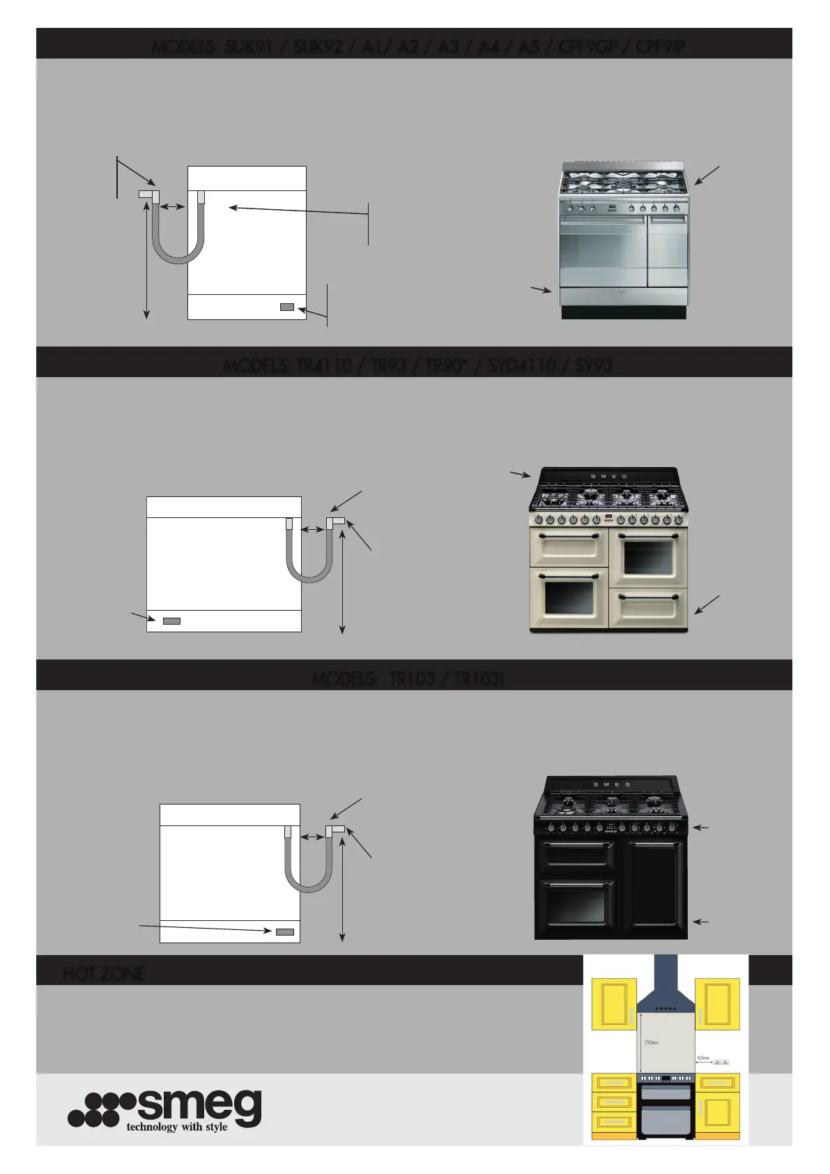
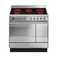
The gas bayonet tting must terminate to the left hand side of the cooker when viewed from the rear and must be within 100mm from the
edge of left hand side, it must not be directly behind the appliance. The bayonet tting must be no higher than 700mm and no lower than
600mm from the oor.
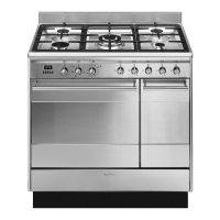
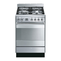
The gas bayonet tting must terminate to the right hand side of the cooker when viewed from the rear and must be within 100mm from the
edge of right hand side, it must not be directly behind the appliance. The bayonet tting must be no higher than 700mm and no lower than
600mm from the oor.
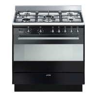
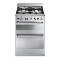
The gas bayonet tting must terminate to the right hand side of the cooker when viewed from the rear and must be within 100mm from the
edge of right hand side, it must not be directly behind the appliance. The bayonet tting must be no higher than 700mm and no lower than
600mm from the oor.
Gas
supply
point
Electrical
connection
point
MODELS: SUK91 / SUK92 / A1/ A2 / A3 / A4 / A5 / CPF9GP / CPF9IP
MODELS: TR4110 / TR93 / TR90* / SYD4110 / SY93
MODELS: TR103 / TR103I
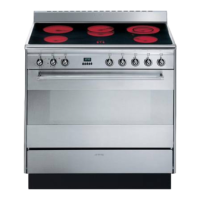
HOT ZONE
A 15mm BSP
socket elbow
(bayonet tting)
A 15mm BSP
socket elbow
(bayonet tting)
Gas
supply
point
Gas
supply
point
Gas
supply
point
100mm
100mm
600mm to 700mm600mm to 700mm
Electrical
connection
point
Electrical
connection
point
The hot zone is the area directly above your cooker or hob. Before installation please ensure
that this area is free from ammable items including wood, wallpaper, plug sockets, wiring or
an overhanging boiler. Unfortunately, if we arrive and the hot zone isn’t clear, we may not be
able to complete your connection.
VIEW FROM REAR
VIEW FROM REAR
Gas
supply
point
Electrical
connection
point
A 15mm BSP
socket elbow
(bayonet tting)
Gas
supply
point
100mm
600mm to 700mm
Electrical
connection
point
VIEW FROM REAR
Electrical
connection
point
*The appliance must be secured to the wall using the brackets or chain provided