4. INSTALLATION
S,\\U\'
by
Dometic
GROUP
N,"I~"
by
Dometic
GROUP
5.
SERVICING
iii
4.7
Duplicate
data
plate
5
SERVICING
After installation,
the
data plate may be consulted
by
opening
the
door
of
the
oven
or
of
the
grill
compartments,
or
on
the
back
of
the
instructions manual.
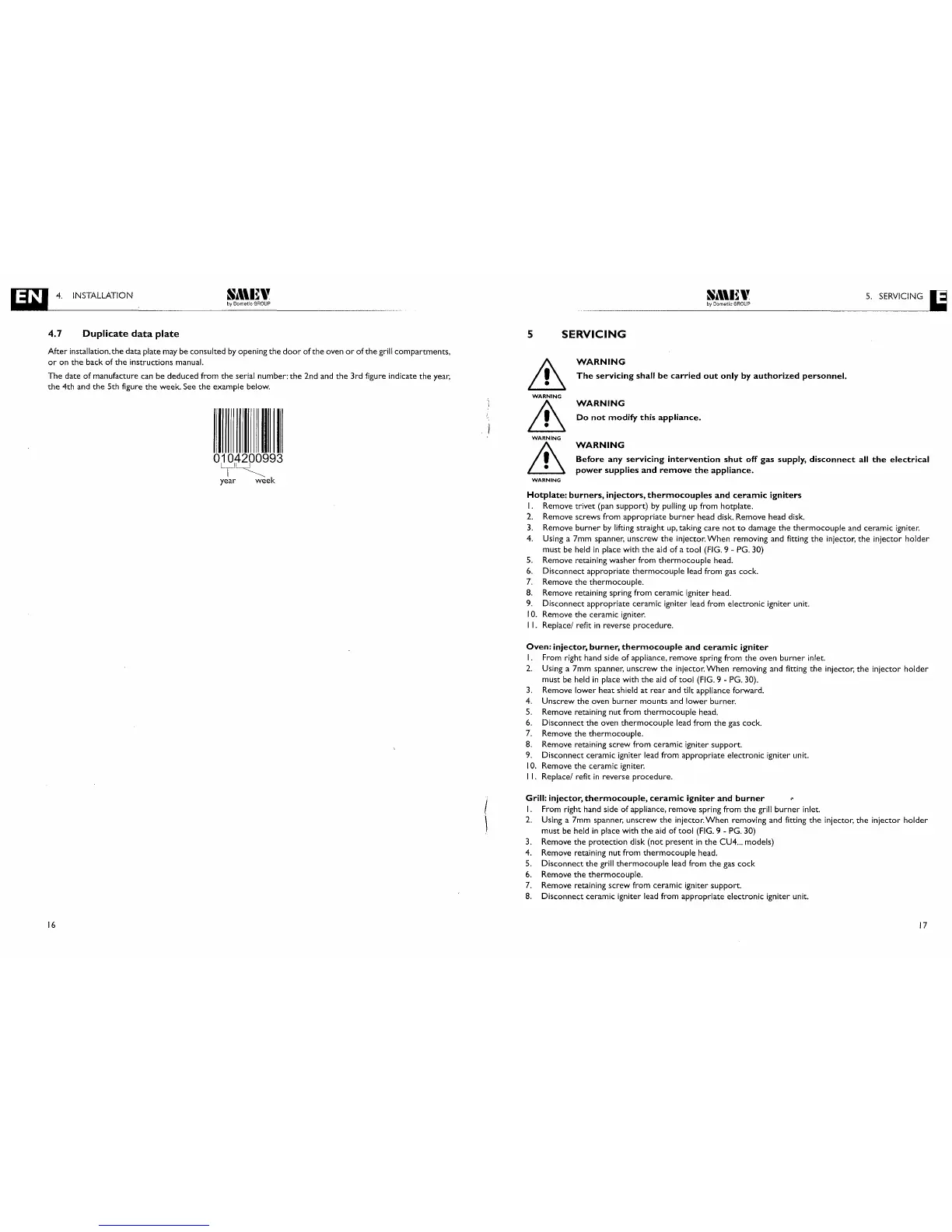
The
date
of
manufacture can be deduced from
the
serial number:
the
2nd and
the
3rd figure indicate
the
year,
the
4th and
the
5th figure
the
week. See
the
example below.
O~~993
year
week
&
WARNING
&
WARNING
&
WARNING
WARNING
The
servicing
shall
be
carried
out
only
by
authorized
personnel.
WARNING
Do
not
modify
this
appliance.
WARNING
Before
any
servicing
intervention
shut
off
gas
supply,
disconnect
all
the
electrical
power
supplies
and
remove
the
appliance.
16
Hotplate:
burners,
injectors,
thermocouples
and
ceramic
igniters
I.
Remove trivet (pan
support)
by
pulling
up
from hotplate.
2.
Remove screws from appropriate
burner
head disk. Remove head disk.
3.
Remove
burner
by
lifting straight
up,
taking
care
not
to
damage
the
thermocouple
and ceramic igniter.
4. Using a 7mm spanner, unscrew
the
injector.
When
removing and fitting
the
injector,
the
injector holder
must be held
in
place with
the
aid
of
a
tool
(FIG. 9 - PG. 30)
5.
Remove retaining
washer
from
thermocouple
head.
6.
Disconnect appropriate
thermocouple
lead from gas cock.
7.
Remove
the
thermocouple.
8.
Remove retaining spring from ceramic igniter head.
9.
Disconnect appropriate ceramic igniter lead from electronic igniter unit.
10.
Remove
the
ceramic igniter.
I
I.
Replace/ refit
in
reverse
procedure.
Oven:
injector,
burner,
thermocouple
and
ceramic
igniter
I.
From right hand side
of
appliance, remove spring from
the
oven
burner
inlet.
2.
Using a 7mm spanner, unscrew
the
injector.
When
removing and fitting
the
injector,
the
injector
holder
must be held
in
place with
the
aid
of
tool
(FIG. 9 - PG. 30).
3.
Remove
lower
heat
shield
at
rear
and tilt appliance forward.
4. Unscrew
the
oven
burner
mounts and
lower
burner.
5.
Remove retaining
nut
from
thermocouple
head.
6.
Disconnect
the
oven
thermocouple
lead from
the
gas cock.
7.
Remove
the
thermocouple.
8.
Remove retaining
screw
from ceramic igniter
support.
9.
Disconnect ceramic igniter lead from appropriate electronic igniter unit.
10.
Remove
the
ceramic igniter.
I
I.
Replace/ refit
in
reverse
procedure.
Grill:
injector,
thermocouple,
ceramic
igniter
and
burner
I.
From right hand side
of
appliance, remove spring from
the
grill
burner
inlet.
2.
Using a 7mm spanner, unscrew
the
injector.
When
removing and fitting
the
injector,
the
injector
holder
must be held
in
place with
the
aid
of
tool
(FIG.
9 -
PG.
30)
3.
Remove
the
protection
disk
(not
present
in
the
CU4
...
models)
4. Remove retaining nut from
thermocouple
head.
5.
Disconnect
the
grill
thermocouple
lead from
the
gas
cock
6.
Remove
the
thermocouple.
7.
Remove retaining
screw
from ceramic igniter
support.
8.
Disconnect ceramic igniter lead from appropriate electronic igniter unit.
17