INSTALLATION AND OPERATING INSTRUCTIONS
B. STEAM BOILER INDIRECT WATER
HEATER PIPING
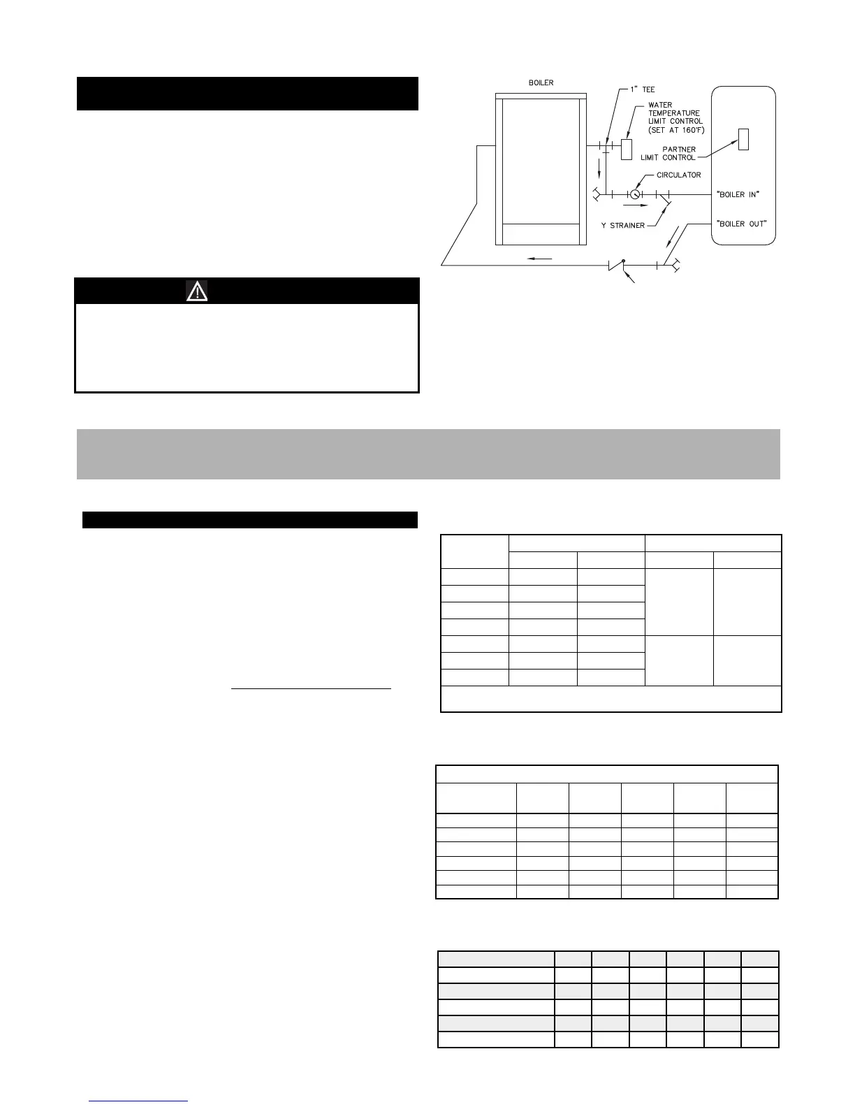
1. See Figure 4.2 for typical installation.
2. Install Boiler Water Temperature Limit Control in 1"
Tee on supply connection (same side of boiler as low
water cut-off). Set Limit at 160°F to avoid steam
generation during periods when only the domestic
water is calling for heat.
3. Install circulator and strainer in supply piping. Install
check valve to prevent gravity circulation.
Maintain water level near normal water line to avoid
steam generation during periods when only the
domestic water is calling for heat.
Tank performance reduced when supplied by steam
boiler.
NOTICE
Figure 4.2: Typical Steam Boiler Indirect
Water Heater Piping
A. INSTALLATION
1. Pipe gas to the boiler in accordance with local codes.
In the absence of local regulations refer to the
National Fuel Gas Code, ANSI Z223.1/NFPA 54.
2. Size and install the gas supply piping to provide a
supply of gas sufficient to meet the maximum demand
of all appliances without excessive pressure drop.
3. The rate of gas to be provided to the boiler can be
determined by:
Obtain the gas heating value of the gas from the gas
supplier. As an alternative use Table 5.1.
4. Table 5.2 shows the maximum flow capacity of
several pipe sizes based on 0.3 inches of water
pressure drop. These values are based on a specific
gravity of 0.60. Apply the factors indicated in Table
5.3 for gas with specific gravity other than 0.60 to
obtain corrected capacities.
5. FUEL PIPING
Based on Specific Gravity of 0.60
Pipe Length
(Feet)
1/2"
Pipe
3/4"
Pipe
1"
Pipe
1-1/4"
Pipe
1-1/2"
Pipe
10 132 278 520 1,050 1,600
20 92 190 350 730 1,100
30 73 152 285 590 890
40 63 130 245 500 760
50 56 115 215 440 670
60 50 105 195 400 610
Table 5.2: Maximum Capacity of Pipe in CFH for a
Pressure Drop of 0.3" of Water
Table 5.3: Maximum Capacity Correction Factors
Specific Gravity other than 0.60
Table 5.1: Gas Input & Valve Inlet
Specific Gravity 0.50 0.55 0.60 0.65 0.70 0.75
Correction Factor 1.10 1.04 1.00 0.96 0.93 0.90
Specific Gravity 0.80 0.85 0.90 1.00 1.10 1.20
Correction Factor 0.87 0.84 0.82 0.78 0.74 0.71
Specific Gravity 1.30 1.40 1.50 1.60 1.70 1.80
Correction Factor 0.68 0.66 0.63 0.61 0.59 0.58
Boiler Input (BTU/HR)
CFH =
Gas Heating Value (BTU/FT³)
Model
Gas Input
1
(CFH) Gas Valve Inlet
2
(NPT)
Nat. Gas LP Gas Nat. Gat LP Gas
88 88.5 35.4
1/2" 1/2"
118 118.0 47.2
147 147.5 59.0
177 177.0 70.8
206 206.5 82.6
3/4" 3/4"
236 236.0 94.4
288 287.5 115.0
1. Natural Gas Based on 1000 Btu./Cubic Foot, LP Gas Based on 2500 Btu./Cubic Foot.
2. See instructions for sizing gas supply piping.
10