B. OPERATION
1. Assure that the gas supply pressure to the boiler is
regulated to 1/2 psi or less (approx. 13.5 inches of
water).
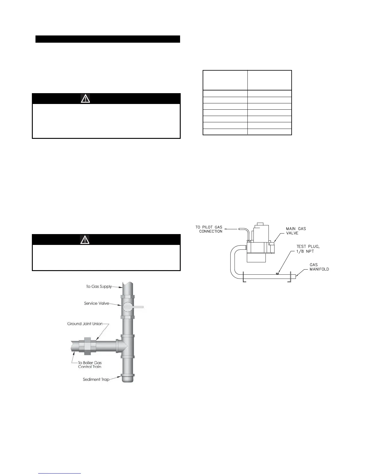
2. Install a service valve, sediment trap, and ground
joint union at the gas supply connection as shown in
Figure 5.1.
3. Check piping for leaks. Use an approved gas
detector or a non-corrosive leak detection fluid. If
leaks are found, turn off all gas supply to the
appliance and repair as necessary.
4. The boiler and its individual shut off valve must be
disconnected from the gas supply piping system
during any pressure testing of that system at test
pressures in excess of 1/2 psi (3.5kPa).
The boiler must be isolated from the gas supply
piping system by closing its individual manual shut
off valve during any pressure testing of the gas
supply piping system at test pressures equal to or less
than 1/2 psi (3.5 kPa).
5. Refer to table 5.4 for minimum supply pressure for
the purpose of input adjustment.
6. Install the boiler such that the gas ignition system
components are protected from water (dripping,
spraying, rain, etc.) during appliance operation and
service (circulator replacement, condensate trap
clean out, control replacement, etc.)
7. The boiler and its gas connection must be leak tested
before placing the boiler in operation.
8. Typical gas train manifold is illustrated in Figure 5.2.
11
INSTALLATION AND OPERATING INSTRUCTIONS
Do not subject the boiler gas valve to pressure in
excess of 1/2 psi (3.5 kPa). Doing so may damage the
valve.
CAUTION
Use a pipe joint sealing compound that is resistant to
the action of liquefied petroleum gas. A non-resistant
compound may lose sealing ability in the presence of
this gas, resulting in a gas leak and fire or explosion
potential.
CAUTION
Figure 5.1
Model
Supply
Pressure
(in. Water)
88 5.00
118 5.00
147 5.00
177 5.35
206 5.00
236 5.00
288 5.56
Table 5.4: Minimum Supply
Pressure Natural Gas
Figure 5.2: Gas Train Manifold