504-2033 Iss. 1j 8 April 2005
4. Check condition of cylinder key
i) Replace if cracking is apparent.
ii) Check attachment cable is not frayed or damaged. Replace if necessary.
5. Check Regulator output
i) Fit a new seal (500-276) to the Regulator Assembly.
ii) Connect the pin-index yoke to a cylinder at least three quarters full.
iii) Connect the Test Unit to the outlet connector of the Regulator Assembly.
iv) Ensure that the Test Unit output is pointed away from the operator and that the flow/no-
flow switch is in the ‘Off’ (no-flow) position. Open the cylinder valve slowly allowing
gas into the regulator and the Test Unit. With no flow the pressure gauge on the Test
Unit will show the static output pressure of the regulator. Record this pressure which
should be between 50 - 80 psi (345-552 kPa) (50-70 psi (345-483kPa) for CE regulator
assemblies).
v) Slide the flow/no-flow switch to the ‘On’ (flow) position. This allows gas to flow
through the regulator and out of the Test Unit. The pressure gauge on the Test Unit
now shows the dynamic output pressure of the regulator. Record the result and switch
off the flow as soon as the reading is noted. This dynamic pressure will be lower than
the previous static pressure but should be no less than 45 psi (310 kPa).
vi) Re-check the static pressure reading and in particular check that it does not creep
continuously higher such that it eventually exceeds the upper allowed pressure of 80 psi
(552 kPa) (70 psi (483 kPa) for CE regulators). If the pressure continues to creep
upwards the main valve seat is leaking and the regulator needs corrective servicing.
vii) The above procedure should be repeated using a cylinder not more than a quarter full.
viii) Close the cylinder valve. The contents gauge should maintain a constant reading.
If the pressure decays at a visible rate, a leak is occurring and corrective servicing is
required.
ix) Vent the pressure by sliding the Test Unit switch to the ‘On’ position and then remove
the Test Unit.
x) Re-open the cylinder valve slowly, observe the contents gauge, then close the cylinder
valve. The gauge should maintain a constant reading. If the pressure decays at a
visible rate the outlet connector/s may be leaking and need corrective servicing.
xi) Where a Constant Flow Selector Head is fitted (500-A958) check the performance as
follows:
(a) Connect a calibrated flowmeter (e.g. 2-25 L/min; 500-82636) to the outlet
connector of the Flow Head.
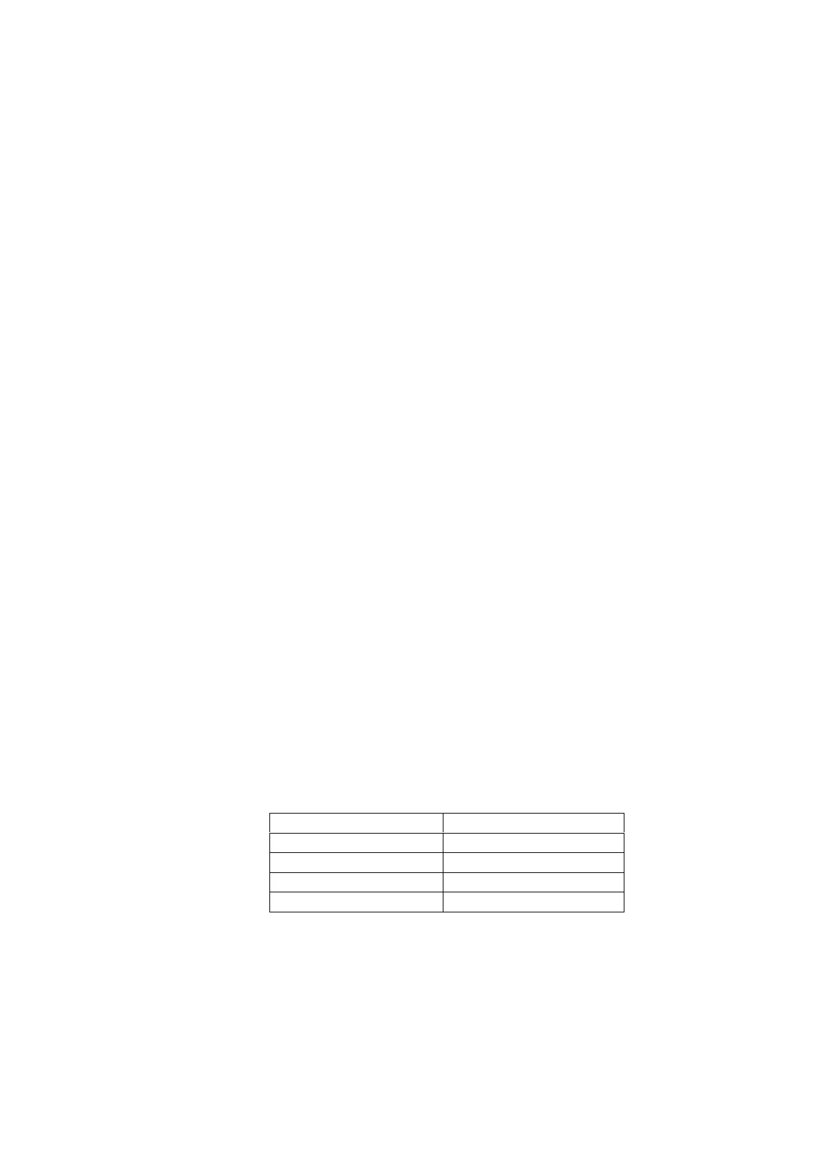
(b) Using the table below check performance of the Flow Head across the range:
Set Flow L/min Actual flow L/min
2 1.8 – 2.2
5 4.5 – 5.5
10 9.5 – 10.5
15 14.5 – 15.5
xii) Replace the Regulator Assembly if any of the above checks fail or repair as
detailed in the High Pressure Regulator Assembly On-Site Routine Service
Procedure (504-2008).