TRAK MODEL 9200 MODULAR FREQUENCY/TIME SYSTEM
3-2
TM4400013 REV. D
3-3 DIGITAL DISTRIBUTION MODULES
Refer to the Model 9100 technical manual section 3-2 for DDM and TEL module configurations. The TEL is
described in the following paragraph.
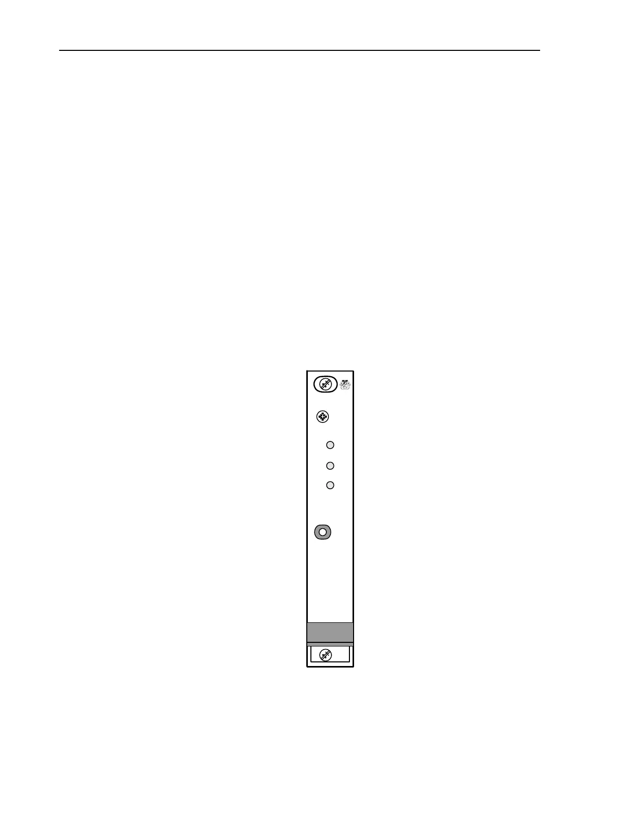
3-3-1 TERMINATOR and FAULT LOGIC, A15
The Model 9250 Terminator and Fault Logic front panel shown in Figure 3-4 contains the following LED
indicators:
FAULT red, module fault summation
ON LINE green, indicates module is on line
STANDBY green, indicated module is in standby (not used)
The Model 9250-1 Terminator and Fault Logic front panel shown in Figure 3-4 contains the following switches:
FAULT RESET Pressing FAULT RESET clears any latched faults in the DDU(s).
Figure 3-2. Model 9250 Terminator and Fault Logic (TFL) A15
FAULT
TRAK
SYSTEMS
TFL
ON LINE
STANDBY
FAULT
RESET
 Loading...