TRAK MODEL 9100 MODULAR FREQUENCY/TIME SYSTEM
2-2
TM4400013 Rev. D
2-5 INPUT POWER
The standard Model 9100 is equipped with two input AC power outlets. The system operates from 100 to 240
VAC ± 10%, with no voltage selection required. If system is configured with redundant power supplies, connect
both AC power cords. If system is configured with a single power supply, connect AC power cord to AC INPUT
A. for DC power input options refer to Appendix D.
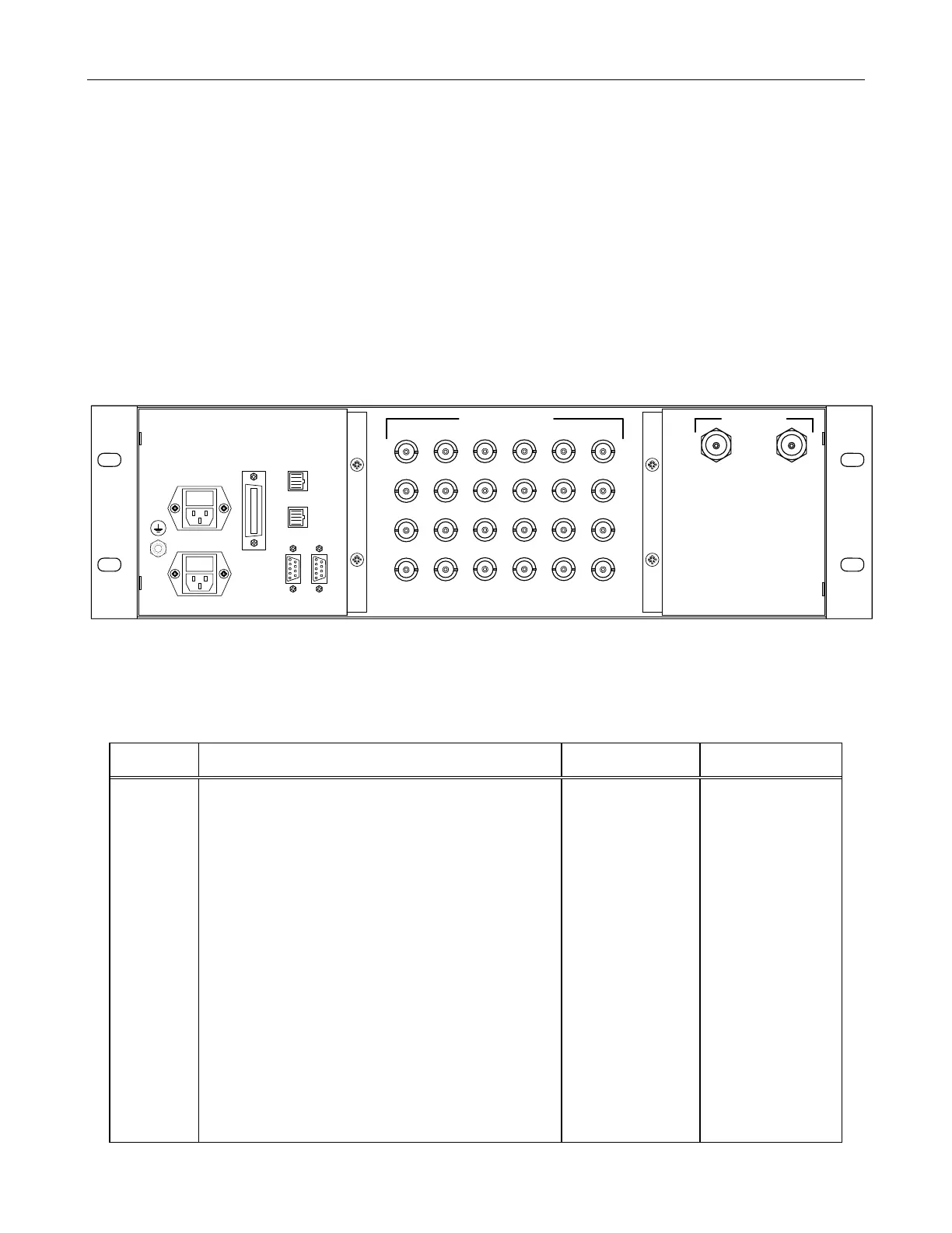
2-6 REAR PANEL CONNECTORS and FUSES
The Model 9100 rear panel is shown in Figure 2-1. All connectors, fuses, and indicators are described in Table
2-1. Multi-pin connector pin connections are provided in paragraph 2-7
Figure 2-1. Model 9100 Rear Panel
Table 2-1. Rear Panel Connectors and Fuses
REF
DES
FUNCTION CHASSIS
CONNECTOR
MATING
CONNECTOR
J1 & J2 Connection to GPS antenna. J1 connects antenna to
GPS Reference Module A1and J2 connects antenna to
GPS Reference Module A2.
N female (2) Antenna Lead- in
cable
J3 & J4 (NOT USED)
J5 – J28 Reference Outputs BNC female (24) BNC male
J29 10 BaseT Ethernet (NTS/NTP) RJ45 female RJ45 male
J30 Alarms, Major and Minor RJ45 female RJ45 male
J31 TOD (Time of Day) DB-9 female (2) DB-9 male
J32 RS-232 I/O DB-9 female (2) DB-9 male
J33 Reference Outputs (to Digital Distribution Unit) AMP 554088-1 IEEE-488 Interface
Cable, with metal
shell and shielded
cable, 1 meter.
Cable supplied with
Model 9200
FL1 100 to 240 Vac, power to PS A (A11) IEC-320 type Power Cord
F1 3 amp slow-blow fuse for PS A (A11) and spare fuse Installed in FL1
FL2 100 to 240 Vac power to PSB ( A12) IEC-320 type Power Cord
F2 3 amp slow-blow fuse for PSB (A12) and spare fuse Installed in FL2
E1
FL1/F1
FL2/F2 J33
J29
J30
J31
J32
J25
J26
J27
J28
J21
J22
J23
J24
J17
J18
J19
J20
J13
J14
J15
J16
J9
J10
J11
J12
J5
J6
J7
J8
J2 J1
FREQUENCY OUTPUTS
123456
AAAAAA
BBBBBB
CCCCCC
DDDDDD
AB
GPS ANTENNA
GND
AC INPUT A
AC INPUT B
REFERENCE
OUTPUTS
10
BASE T
ALARMS
TOD
RS-232
I/O
LINE
100-240 VAC
1.2A TO 0.7A
48-63 Hz