TRAK MODEL 9200 MODULAR FREQUENCY/TIME SYSTEM
3-1
TM4400013 REV. D
CHAPTER 3
OPERATION
3-1 GENERAL
This chapter covers the operation of the Model 9200 including a description of front and rear panel controls and
indicators, initial synchronization and fault detection.
3-2 FRONT PANEL CONTROLS AND INDICATORS
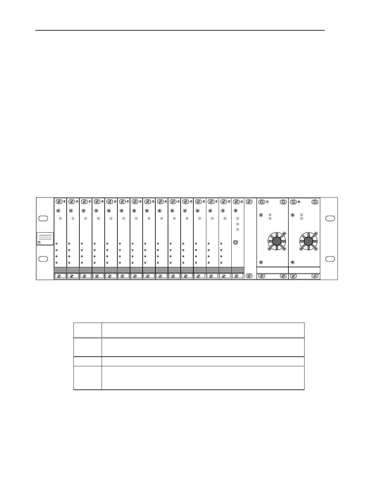
The Model 9200 front panel is shown in Figure 3-1. Table 3-1 lists each module with its system reference
designator and gives a description of the Module. A view of each module front panel along with a description of
controls and indicators is also provided. Further details for each module are given in Appendix G.
Figure 3-1. Model 9200 Front Panel
Table 3-1. Model 9200 Front-Panel Module Locations and Functions
REF
DES
DESCRIPTION
A1-
A14
DDM and/or TEL modules may be installed in these locations.
A15, TFL module position.
A17,
A18
Power Supply module. Provides Diode “OR’ed” +5, +15, and -15 Vdc to
all modules. Two modules are used for dual redundancy. May be AC or
optional 20-60 Vdc input power supplies.
TRAK Systems
OUT A
OUT B
OUT C
OUT D
FAULT
TRAK
SYSTEMS
DDM
OUT A
OUT B
OUT C
OUT D
FAULT
TRAK
SYSTEMS
DDM
OUT A
OUT B
OUT C
OUT D
FAULT
TRAK
SYSTEMS
DDM
OUT A
OUT B
OUT C
OUT D
FAULT
TRAK
SYSTEMS
DDM
OUT A
OUT B
OUT C
OUT D
FAULT
TRAK
SYSTEMS
DDM
OUT A
OUT B
OUT C
OUT D
FAULT
TRAK
SYSTEMS
DDM
OUT A
OUT B
OUT C
OUT D
FAULT
TRAK
SYSTEMS
DDM
OUT A
OUT B
OUT C
OUT D
FAULT
TRAK
SYSTEMS
DDM
OUT A
OUT B
OUT C
OUT D
FAULT
TRAK
SYSTEMS
DDM
OUT A
OUT B
OUT C
OUT D
FAULT
TRAK
SYSTEMS
DDM
OUT A
OUT B
OUT C
OUT D
FAULT
TRAK
SYSTEMS
DDM
OUT A
OUT B
OUT C
OUT D
FAULT
TRAK
SYSTEMS
DDM
OUT A
OUT B
OUT C
OUT D
FAULT
TRAK
SYSTEMS
DDM
OUT A
OUT B
OUT C
OUT D
FAULT
TRAK
SYSTEMS
DDM
FAULT
+5 VDC
AC / DC P.S.
TRAK
SYSTEMS
A1 A2 A3 A4 A5 A6 A7 A8 A9 A10 A11 A12 A13 A14 A15 A16 A17 A18
FAULT
TRAK
SYSTEMS
TFL
ON LINE
STANDBY
FAULT
RESET
FAULT
+5 VDC
AC / DC P.S.
TRAK
SYSTEMS
 Loading...