TRAK MODEL 9100 MODULAR FREQUENCY/TIME SYSTEM
3-2
TM4400013 Rev D
3-2.1. GPS Reference Modules, A1 and A2
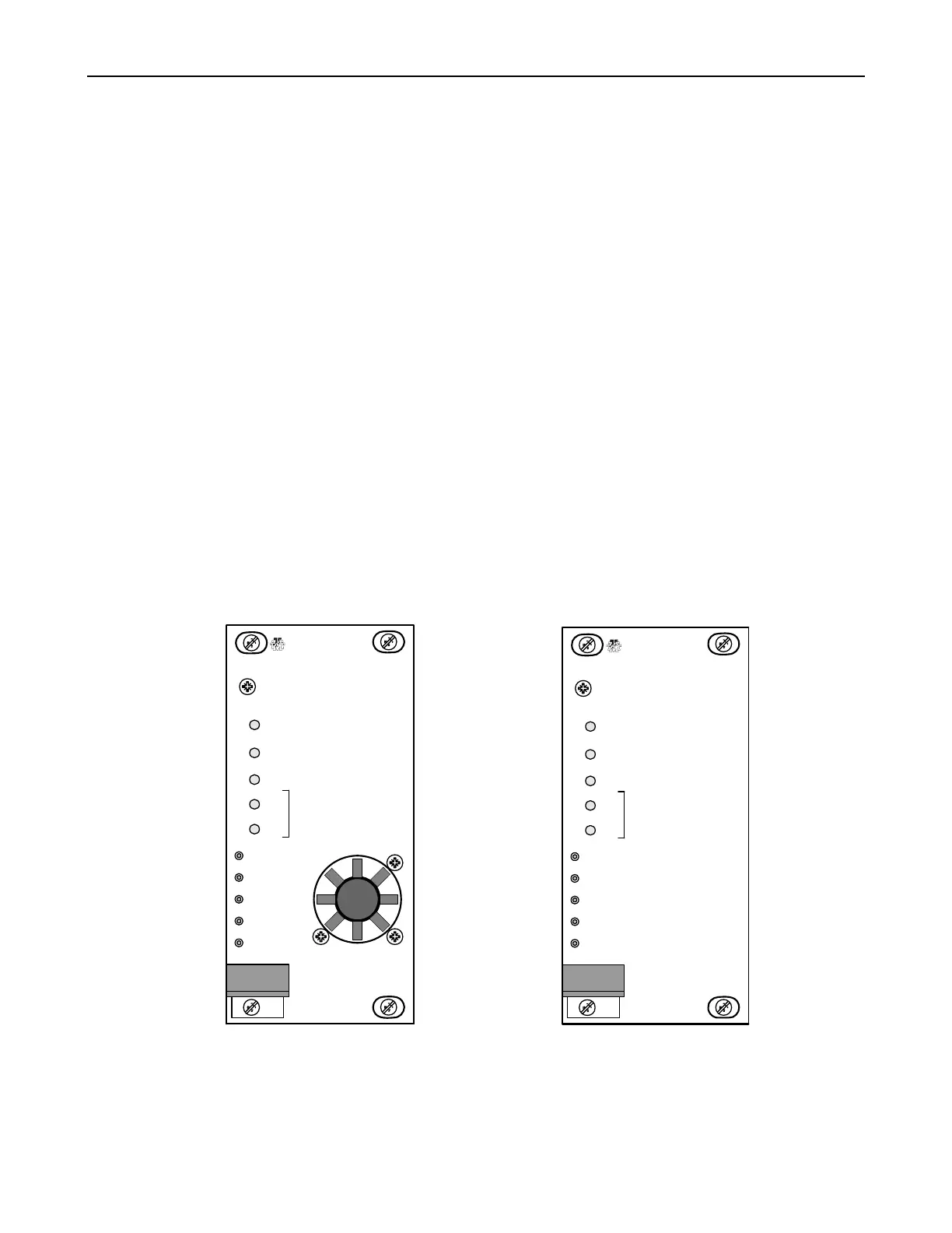
The Model 9101 GPS Reference Module front panel is shown in Figure 3-2. Descriptions of the indicators and
test points are given below.
FAULT Red, module fault summation
ON LINE Green, indicates module is the on line reference
STANDBY Green, indicates module is in standby
LOCKED Green, indicates internal oscillator is within ± 400 ns of GPS. At power up and until the
module is locked the indicator flashes, during this time the 1 PPS, 5 MPPS and
Composite signal outputs are muted.
TRACKING Green, indicates GPS is tracking satellites
The Model 9101 GPS Reference Module front panels shown in Figure 3-2 contains the following test points:
1 PPS Module 1 PPS monitor
5 MPPS Module 5 MPPS monitor
COMPOSITE Module Composite monitor
IRIG-B Module IRIG-B modulated time code monitor
GND Ground
Figure 3-2. Model 9101 GPS Reference Module (GPS)
NOTE: GPS Reference modules that contain a front panel fan have an internal Rubidium oscillator. Modules
without the fan contain a crystal oscillator.
GPS REFERENCE
FAULT
TRAK
SYSTEMS
ON LINE
STANDBY
LOCKED
TRACKING
1 PPS
5 MPPS
COMPOSITE
IRIG B
GND
GPS
GPS REFERENCE
FAULT
TRAK
SYSTEMS
ON LINE
STANDBY
LOCKED
TRACKING
1 PPS
5 MPPS
COMPOSITE
IRIG B
GND
GPS
 Loading...