Do you have a question about the Smithy Granite 1340 Series and is the answer not in the manual?
Procedure for checking crates and cartons for signs of loss or damage upon arrival.
Essential safety warnings, including wearing gloves and safety glasses.
Steps for removing the machine from the pallet using a hoist or mechanical lift.
Procedures for manual removal and lifting, often requiring multiple people.
Specific bolts, washers, and nuts required for securing the machine.
Methods for positioning and aligning the machine base with mounting holes.
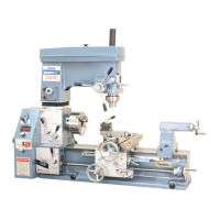
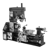
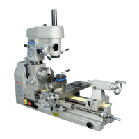
The Smithy metal-working machine is a versatile and robust piece of equipment designed for various metal fabrication tasks, offering users the ability to perform milling, turning, and drilling operations. Its construction is geared towards providing years of quality work and enjoyment, provided it is set up and maintained properly. The machine is accompanied by a comprehensive set of documentation, including a detailed operating guide, a reference manual, and a DVD, all intended to help users familiarize themselves with its capabilities and ensure safe and effective operation.
The Smithy machine serves as a multi-purpose metal-working tool, capable of handling a range of tasks from precision turning on a lathe to intricate milling and drilling operations. This versatility makes it suitable for hobbyists and professionals alike who require a single machine to perform multiple functions. The core design integrates the functionalities of a lathe and a mill, allowing users to switch between modes or perform combined operations as needed.
For turning operations, the machine features a headstock and a tailstock, enabling the user to secure and rotate workpieces for shaping. The carriage assembly, which includes the cross slide and tool post, allows for precise movement of cutting tools along the workpiece. Milling operations are facilitated by a millhead that can be positioned and adjusted to perform various cuts, including face milling, end milling, and drilling. The machine's robust construction ensures stability during these operations, contributing to accuracy and finish quality.
Power requirements for the Smithy machine vary by model, with some requiring a 110-volt AC circuit protected by a 20-ampere breaker, and others needing a 220-volt AC circuit single phase protected by a 15-ampere breaker. It is strongly recommended to use a dedicated circuit for the machine and to avoid extension cords, or if one must be used, to ensure it is rated for at least 20-amperes. This ensures a stable power supply and prevents electrical issues during operation.
Setting up the Smithy machine requires careful planning and execution to ensure safety and optimal performance. The first step involves preparing a suitable work bench. The bench must be capable of supporting the machine's weight, which can be substantial (up to 900 pounds or more for fully assembled models), plus an additional 300 pounds for tools, holding devices, and work material. Smithy offers optional work benches specifically designed to support its machines, but users can also construct their own, provided it is sturdy, rigid, level, and well-supported. The ideal height for the bench places the machine controls at waist level for ergonomic operation. The work bench should also be located in a vibration-free area with a floor designed to support the full weight of the setup.
Clearance around the machine is crucial for safe and efficient operation. At least 3 to 4 feet of clearance is recommended on the operating side (front) of the machine. Additional clearance is needed for specific components: 2 to 3 feet for the gear/pulley enclosure to allow for opening and passing stock through the spindle, 2 to 3 feet for the millhead to swing and for access to the back of the machine, and sufficient space at the tailstock end to allow stock to hang over the end of the bed.
Receiving the machine involves careful inspection. Upon arrival, users should thoroughly check all crates and cartons for signs of loss or damage. If any damage is observed, it should be noted on the delivery receipt while the shipping company employee is present. The crate itself is designed to protect the machine, so damage to the crate does not necessarily mean the machine is damaged, but documenting it makes any potential claim easier to substantiate.
Moving the machine from its pallet to the work bench can be done either with mechanical power (using a hoist or mechanical lift) or without, by disassembling parts of the machine to reduce weight. If using mechanical power, Smithy recommends having at least one additional person present for safety. The lifting procedure involves removing hold-down straps, protective coverings, and any components that could be damaged by lifting chains or straps. The machine's lifting handles are designed to facilitate this process. When lifting, it's important to balance the weight by moving the table and tailstock as far to the right as possible. Lifting straps should be securely attached to the lifting handles, ensuring they do not cross from left to right on the operator's side to maintain stability.
If mechanical power is not available, the machine can be disassembled to reduce its weight for manual lifting. This involves removing the millhead, tailstock, and lathe chuck. The millhead, which can weigh up to 100 pounds, requires careful removal, often involving scoring paint lines and removing capscrews. The tailstock is removed by loosening its locking handle and sliding it off the bed, with care taken to prevent the gib and locking pin from falling out. Lathe chuck removal varies by model, but generally involves loosening bolts or turning square sockets. The carriage assembly can also be removed, though this is not recommended unless absolutely necessary due to the risk of small parts falling into the apron assembly. When lifting manually, proper lifting techniques, such as squatting and using leg muscles, are emphasized to prevent back injury.
Securing the machine to the work bench is a critical final step. The machine base has four mounting-bolt holes. Smithy provides recommendations for mounting hardware based on the specific bench model (e.g., metal chip tray bench, maple top bench). If using a custom bench, equivalent hardware should be used, adjusting bolt length for bench top thickness. Aligning the machine involves suspending it just above the bench top with a hoist, using bolts in opposite corners as guides, and then gently lowering it into position. If drilling holes, the machine is temporarily placed, hole locations marked, then moved to drill pilot holes before final placement and tightening.
While the manual primarily focuses on setup, the emphasis on proper handling and securing the machine implicitly highlights key maintenance considerations. The recommendation to keep the crate in case the machine needs to be returned for repair suggests that the machine is designed for longevity but may require servicing over its lifespan. The detailed instructions for disassembling and reassembling components for moving the machine also serve as a guide for potential future maintenance or repair tasks that might require access to internal parts.
The warning about small parts falling into the apron assembly if the carriage is removed underscores the importance of careful handling and reassembly to prevent damage and ensure smooth operation. This implies that regular inspection of these areas for loose parts or debris would be a good maintenance practice.
The need for a stable and vibration-free work environment, along with proper electrical connections, contributes to the machine's overall health and longevity. Vibrations can lead to wear and tear on components, while incorrect electrical supply can damage the motor or control systems. Therefore, maintaining the integrity of the work environment and electrical setup is an ongoing maintenance aspect.
In summary, the Smithy metal-working machine is a comprehensive tool designed for durability and versatility. Its usage involves a meticulous setup process, from preparing the workspace and receiving the shipment to carefully moving and securing the machine. While explicit maintenance schedules are not detailed in this quick-start guide, the instructions provided lay the groundwork for understanding the machine's construction and the care required to ensure its long-term performance and safety.
| Swing Over Bed | 13 in |
|---|---|
| Spindle Taper | MT5 |
| Tailstock Taper | MT3 |
| Distance Between Centers | 40 inches (1016 mm) |
| Thread Cutting Range | 4 TPI |